Plumbing Re-design Blog

V

vince-1961

Guest
Hi folks. I am re-doing my plumbing. Because I am extremely sensitive to constant humming noises, like electric motors and fans (can we say pumps, computers and refridgerators?), I have GOT to place the pumps in another room before I go insane. My choices were the garage about 15 feet to the right of the aquarium, or outside just behind the aquarium. I chose outside, because the exterior wall already has an opening cut into it as required by local code on flooding and because I can discharge water directly to ground during water changes.
I am starting with the addition of a closed-loop powered by a ReefFlo Dart, the stats on which are 3,600 gph at 0 head using full 2" input and 1.5" output. Restricting the out lines to smaller ID powers it down and uses less wattage. Will use two 1" SCWD for wavemakers after a run of 1.5" leading to a Tee out of which will come two 1" lines.
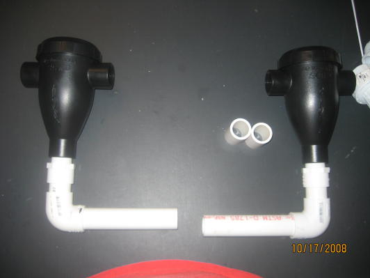
We begin outside.
Attachment 210592
Attachment 210596
I've already forgotten one thing on this dry fit run, namely the addition of a Tee in between the two 45 degree turns on the 2" drain line. Off that Tee, I will put a ball valve and a pipe leading away from the pump for water changes. No more siphoning into 30 gallon RubberMaid trash cans and making a mess in the process!!!
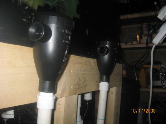
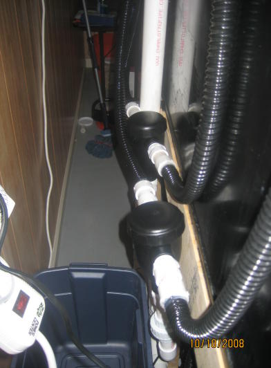
Now, the pump has to be removable in case it needs servicing, but I don't want to break down whole system or lose the water in the pipes as the pump is not self-priming. So just on the inside of the wall, I have a single union ball valve on both the drain and return lines. The ball valve stays in place, keeping water in the pipe while the union slides out of the wall and then that section can be unscrewed from the pump.
Attachment 210595
Attachment 210598
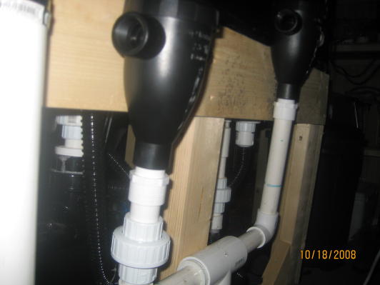
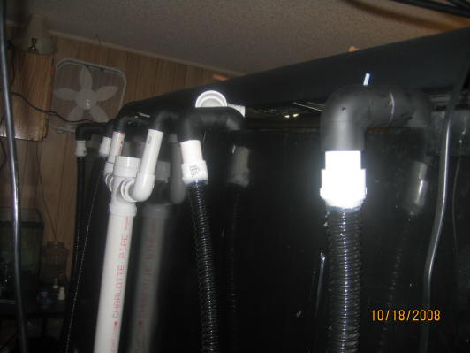
Here is what is at the top of the 2" drain line. The idea is to attach 1" lines from the DT on each side. The middle part has a cap. The purpose of the cap is to provide an opening through which I can pour water to fill up the 2" drain line all the way to the pump, because the pump is not self-priming. I am worried that this is going to create an air pocket which may make noise. On the other hand, the copper plumbing for all bathtubs and showers has an extra piece leading up with air in it to eliminate "knocking." Maybe the air pocket this opening creates will provide "anti-knock" instead of noise.
Anyone know the answer to this question before I glue this in permanently?
Attachment 210597


V

vince-1961

Guest
I've made water inlets, but am waiting on two SQWD's to arrive.
Note that I changed the inlets for the drains from DT to pump from two 1" strainers per two 1" pipes as shown in the photo with the newspaper to one 1" strainers per 1" pipe. In other words, I eliminated the Tee.
here are the returns, from ledt to right. 4 of them. ....
Attachment 210987
Attachment 210988
Attachment 210989
Attachment 210990
and here is the back of the tank where the returns will connnect.
Attachment 210991
I am waiting on delivery of two SCWD's to finish.


V

vince-1961

Guest
While waiting on SCWDs, I went ahead and did some more of the return and the drain....
Here is the drain, where the two 1" lines in the water come together to form a 2" drain pipe.
Attachment 210993
and this is where the 1.5" return pipe Tee's off into two 1" lines, both of which will connect to the 1" SCWD's once (if ever) they get delivered. From there the two SCWD will each discharge two lines, hence the four return pipes previously displayed.
-Attachment 210992

 
V

vince-1961

Guest
While waiting on SCWDs, I went ahead and did some more of the return and the drain....
Here is the drain, where the two 1" lines in the water come together to form a 2" drain pipe.
Attachment 210993
and this is where the 1.5" return pipe Tee's off into two 1" lines, both of which will connect to the 1" SCWD's once (if ever) they get delivered.
-Attachment 210992
 

cranberry

Active Member
Originally Posted by robertmathern
http:///forum/post/2799313
I would make a cover for the pump. If it is going to be outside so weather dose not destroy it.
Anyone who requires a food hole in their house to be up to code will need more than a cover.
 

scotts

Active Member
Originally Posted by vince-1961
http:///forum/post/2790027
full 2" input and 1.5" output. Restricting the out lines to smaller ID powers it down and uses less wattage.
Correction, this in not correct. Using a smaller diamter outlet pipe will cause less flow, but the pump will pull the same amount of electricity. In fact it may cause it to use more electricity since the pump is operating under a higher pressure.
 
V

vince-1961

Guest
Yes it is outside. It is under a cover, which at present is just a square rubbermaid-type container. By the time I am finished, I'll have two pumps out there and a chiiler, so I'll probably end up building a little mini-shed with a roof made of actual shingles.
What's a "food hole"?
When I am done, I will fill in all open holes with expanding, insulating foam so that no critters and bugs can crawl in. The foam can always be removed easily and costs a whopping $5 per can.
The 1" SCWDs arrived yesterday, so I'll take some good photos of them, including the inner workings, and post them here for general info for anyone who may want to check them out. As it turns out, they do not have barbed fittings for slip on flexible tubing as I had thought, but rather female threads.
This closed loop will be finished Saturday. Assuming it runs w/o leaks, then I will remove sump and re-design the baffles, put the really noisy sump-pump (an old iwaki w/ american motor) outside and re-plumb the DT to sump to DT plumbing.
You know, it just occurred to me that, eventually, I'll probably get into fragging corals, but I'm am not going to go ahead and build plumbing for a frag tank into the system yet. All good things in time.....speaking of which, how about I go REALLY overboard, buy another huge tank, and plumb them together? (just kidding.)
 

spanko

Active Member
So even if you are going to build a shed over the pump(s) to keep the weather out, that being the flood hole for the house, what if you do get a flood, even one that you dosn't cause the house to flood but gets up over the pump heghts??????
 
V

vince-1961

Guest
Originally Posted by Scotts
http:///forum/post/2799364
Correction, this in not correct. Using a smaller diamter outlet pipe will cause less flow, but the pump will pull the same amount of electricity. In fact it may cause it to use more electricity since the pump is operating under a higher pressure.
Scott, the advertisements and the brochure in the box claim that restricting the outflow will cause the pump (ReeFlo Dart) to power down, hence fewer watts consumed.
I personally don't know as I have yet to plug the pump in and run it.
Oh, I forgot to post the correction of the mistake with regard to drainage for water changes. Here it is....
Attachment 211196
Attachment 211197[

 
V

vince-1961

Guest
Originally Posted by spanko
http:///forum/post/2799377
So even if you are going to build a shed over the pump(s) to keep the weather out, that being the flood hole for the house, what if you do get a flood, even one that you dosn't cause the house to flood but gets up over the pump heghts??????

If I get a flood, I'm ...er...ah... not exactly hammered, but the thing a screwdriver does....
Hopefully the island (and my house) will not flood until a hurricane actually hits us!
and if the water level outside gets up to the pump height, my garage, daughter's playroom and aquarium room (in other words, everything downstairs) will also be under water as the pump outside is about level with the concrete floor inside.
 
V

vince-1961

Guest
A little experimentation tonight with the location of the SCWDs. I want to be able to strap them securely to the wood in order to prevent any movement of the units......
Thank God PVC is (relatively) cheap as I used a good 24" worth figuring this out!
Attachment 211193
Yes that red was my belly wearing a red shirt!
Glad I posted this photo! Made me realize that I forgot to install a union under the SWCDs just in case I should ever need to remove them for cleaning or whatever. Funny thing is that I originally laid it out on the ping pong table as having the union. Reckon I must've been distracted by the arrival of girlfriend.....
Attachment 211194
oh yea. Definitely want it further up, so I can strap it to the wood. The absence of a union on the shorter one sure does explain why it's too short to reach the wood. DUH!
Attachment 211195
Okay, just went downstairs and grabbed those two short pieces of PVC shown in 1st pic above (dang,,,, I KNEW I had cut those pieces for a reason...) and used them to connect a union. Imagine that. It fits.
Attachment 211199
well, actually it's a little on the short side.
Attachment 211200
aw shucks! that last pic made me think of how much $ I've spent on PVC. Each of those unions is $5.27 and there are 4 of them shown in that last pic. There are a lot more of them than are shown in that pic, too.


V

vince-1961

Guest
Good Morning! The mayhem from 3 girls, ages 4 to 8, spending the night with my daughter is strewn across the playroom, so let's get back to plumbing...
Got the unions connected, height adjusted, measured flexible tubing (20' for $20 from the outdoor pond section at Lowe's - is ribbed on outside and has smooth ******** walls), cut it and installed the barbs. If I have anything to do with it, this system will not leak. Hence the silicone around the barb fittings.
Attachment 211208
Attachment 211209
By the way, the best way to insert the barbs is to mircrowave, but not boil, about 2" of water in a coffee cup, stick the tubing in the water for 10 seconds or so, then rotate the barb in the direction of the ribbing on the tube while pushing (i.e. - s c r e w ) the barb in. Always gives me blisters! Don't heat the tubing too much, because it melts or will be so weak that water pressure will blow out a wall or you'll poke holes or make cracks in it when you

[hr]
in the barb. Do not overheat.
Attachment 211210
okay, everything seems to fit on this dry run. Of course, when I

[hr]
the threads all the way in and slip the PVC parts all the way together with glue, everything will be a bit shorter. I ought to let the silicone dry for 48 hours before I test the system, but who are we kidding? (That'd be the whole weekend.)
Attachment 211211
Notice the fan hanging from the wall? That's my version of the dinky fans people clip to the edge of the aquarium to blow air across the surface. But then again, this room has no HVAC , except a window unit located in the next room over (the playroom), so the only real ventilation is to open the outside door. Recall that the ground level floor of my house consists of a garage, the aquarium room and the playroom. Three very large rooms that, according to some governmental or flood insurance company genius, are not really supposed to be enclosed, heated, cooled or otherwise actually counted toward the square footage of the house. (yea, right...
)
Attachment 211212


V

vince-1961

Guest
Primed the system with new saltwater. The closed loop adds about 5 gallons to the system.
Attachment 211215
and....
there's one little drip at a barb fitting. Okay, no problem, drain the water out of the pipes and fix it. Take 5 gallon bucket outside to drain. Fill bucket. Close ball valve. Ought to be about a gallon left in the bottom of the pipes, down by the pump. Works like a charm. So easy. I'm pleased.
Go back inside and .....
.....
DISASTER! There is water flowing freely all over the place as it siphons water out of the DT and dumps it on the floor! So, I frantically try to pull each pipe in the DT loose from the elbow to break the siphon. Finally manage to stop the flow of water, although I never had a real chance to see exactly from where the water was flowing. The sump pump is, of course, sucking air by now. Thankfully, it's a concrete basement.
Put the 4 gallons of water in my bucket back into the sump. Drain water out of closed loop pipes. Put it in sump. Shop vac the water off the floor. Set up fans to evaporate remainder and finally get a chance to look at the system.
First thing I find is that I forgot to glue the 1.5" single union ball valve on the discharge side of the pump. Second thing I find is that I am out of PVC cement, but I manage to scrape enough out of the can to do this one joint. Will have to go to store for more before I try to fix anything else.
GRRR......
 
V

vince-1961

Guest
Found a leak in an inconvenient spot, despite the PVC pieces being very solidly fit together. Will try silicone inside and out. Will give it at least a day to dry before I try introducing water to the system again. If this does not work, redoing that one part with all new parts won't be cheap and will require precise measurements, but at least it will be easy. The spot is where union connects to the pipe just b4 the 45 degree turns leading down to the pump, just perfect to allow the drip to land inside the wall !
grrr
Attachment 211228
Attachment 211229
Look down the pipe. See the purple ring? Apparently I did not push the pieces together enough when I cemented them. I filled it with aquarium silicone.
Attachment 211230


robertmathern

Active Member
I figured you would have a few leaks. Thats a cool system though cant wait to see it work. Aquarium sealicone thats what I used on everything and worked great for me. However you need to look into why it is syphoning out of the DT. Most likely just need to drill hole in the return in te DT. Because if you live in a hurricane zone like me (Florida) after Kitrina I did not get power back for 2 months. Not that it matter how long the power is out but you dont want to drain the DT dry that would suck.
 
Top