LED Blue/UV Moonlight Mod...Tutorial needs Help!!!!

asharp13

Member
Hi,
Recently my moonlights in my 24gal Aquapod crapped out on me. I have been toying with the idea of moding my own LED system and integrating it into the hood. I want to add two blue(470nm) LED's and two UV(361nm) LED's to my hood on two separate circuits with separate switches to be able to control them individually. I can handle all the hood modifications but I am looking for some help with the wiring, resistors, power source, etc. I was also wondering if anyone has used blacklights in their tank and if I should be aware of any adverse effects that may come from them.
Here is what I have put together so far:
Radioshaq:
enercell (3/4.5/6/7.5/9/12VDC – 1A) AC-to-DC Power Adapter
enercell Adaptaplug Power Leads (converts the power adapter to a positive and a negative wire)
ledsupply.com:
Blue 30* 5mm LED
http://www.ledsupply.com/l1-0-b5th30-1.php
- Wavelength: 470nm
- Luminous Intensity: 1500mcd typ. @ 20mA
- Max Forward Current: 30mA
- Pulse Current: 100mA for <= 10ms, duty <= 1/10
- Forward Voltage: 3.6V typ. 4.0V max @ 20mA
- Max Reverse Voltage: 5V
- Power Dissipation: 120mW
- Operating Temp: -30 to +85 C
- Soldering Temp: 265 C for 10 secs
- Max Reverse Current: 50uA @ 5V
361nm UV 15* 5mm LED
http://www.ledsupply.com/l5-0-u5th15-1.php
- Wavelength: 361nm
- Luminous Intensity: 750 µW
- Max Forward Current: 30mA
- Pulse Current: 80mA for <= 10ms, duty <= 1/10
- Forward Voltage: 3.8V typ. @ 20mA
- Max Reverse Voltage: 5V
- Power Dissipation: 135mW
- Operating Temp: -20 to +85 C
- Soldering Temp: 265 C for 10 secs
I found this article online and plan to follow it but I would love feedback and suggestions from all of you.
http://unclean.org/howto/led_circuit.html
I am also confused as how to add 2 separate circuits to one power supply and how to calculate what resistors I will need, what voltage to set the adapter to, and how exactly to wire it all together. Hopefully I can detail this tutorial fully, detail my findings, and with help from all of you, create an easy DIY project for future endeavors.
 

scsinet

Active Member
I'm going to derate by about 20&#37; because likely, the LEDs will not last long being driven at these values, as these are "absolute maximum ratings."
I am also assumuing a 12 volt power supply
For a single LED:
Blue LED: 25ma current @ 3.6v fv = 330 ohm, 1 watt resistor.
UV LED: 25ma current @ 3.8v fv = Same thing.
However, if I'm reading this correctly you want to use 30 blue and 15 UV LEDs... so... I'd connect them in series-parallel to reduce the resistor count and increase efficiency. You should be able to do 3 in series...
Blue LEDs: 3 in series, 25ma, 3.6fv = 48 ohm, 1/2 watt resistor
UV LEDs: 3 in series, 25ma, 3.8fv = 24 ohm, 1/2 watt resistor
So what you'd have to do here is assemble (10) groups of (3) series connected LED/resistor, and then wire the 10 groups in parallel. Then you'd do (15) groups of (3) for the UV.
Alternatively, you could do groups of 5 with a larger supply. If you could get a 24 volt supply, you could do (6) groups of (5) with a 240 ohm, 1 watt resistor, and (3) groups of (5) UV LEDs with a 220 ohm, 1 watt resistor.
Ohe word of caution... your LEDs don't seem that powerful. The current figures lead me to believe that these LEDs are pretty weak. What you should be looking at are the Luxeon or Cree 1w or 3w LEDs. They are mounted on a little aluminum heatsink substrate, and you can get optics for them that will focus the light down into the tank. Also, UV LEDs typically do not emit visible light.
 
S

saxman

Guest
you can also do this a much simpler way (i've had a set running 24/7 on a 60 gal for about 6 or 7 years now):
use the 4.5V setting on your supply.
wire the LED's in parallel with a 100 ohm resistor on one leg and you're good to go.
if you want to add the UV's on a separate circuit, just wire them the same way, but run a separate switch to the P/S.
granted, it's not "optimum" (SCSI's way is great, BTW), but it will work fine, and will give you the results you're looking for: EZ and functional.
 

scsinet

Active Member
Are you sure about 100 ohms? For a 3.6fv, 25ma, and a 4.5v supply, I put the resistor value at about 36 ohms (or 39 for a common value).
Working backwards, a 100 ohm resistor on a 4.5v supply with a 3.6fv, would only put 9ma through the LED.
Or is my math wrong?
Wiring LEDs in parallel does work. I'd just be a bit concerned about one LED hogging all of the current, or if a wire comes loose, a catastrophic failure of the remaining LEDs occuring. LEDs appear as a direct short across the line, hence requiring the resistor to regulate the current flow. Ergo in a parallel configuration, there are risks depending on how the wires are run. For example, if you parallel the LEDs from one to the next, with a resistor on one end, current flow will tend to be highest on the LED closest to the resistor, due to voltage drop the further from the supply end.
I'm not trying to say it won't work, just as you said, it's not "optimum." One thing to consider is that in this arrangement, you'll need a very large power resistor, and a larger power supply since (45) LEDs drawing 25ma apiece on a 4.5v line exceeds 1 amp of current draw. This would also be the case if using individual resistors on all LEDs... forgot to mention that this morning.
 

scsinet

Active Member
By the way... there are companies out there that are selling drop in LED retrofit systems for these tanks... if you didn't want to go the DIY route.
 
L

lilredwuck

Guest
I bought a blue LED kit off eb......er that one site, a couple years ago. Wired and ready to go for around $10-15. Just put them in the hood and go. They are WAY brighter than the moonlights that come in the current fixtures, as I could actually SEE stuff in the tank. Just a thought. I think it came with 6, which I used on a 55
 

scsinet

Active Member
I think the OP is trying to actually replace his entire lighting setup with this... judging from the quantities of LEDs he is talking about, I don't know what other plan it could be.
 
S

saxman

Guest
what stuck in my head was "...my moonlights in my 24gal Aquapod crapped out on me." and "I want to add two blue(470nm) LED's and two UV(361nm) LED's to my hood on two separate circuits with separate switches to be able to control them individually."
at any rate, i guess i should have made it more clear...100 ohms on one terminal of each resistor
, and yes, they're simply there as current limiters. if you bump the resistor value down, you could drive the LED's a bit harder, but the way i did it, the LED's are plenty bright and well-derated.
as for semiconductor physics, i deal with that on daily basis...more than i'd like, to be honest (tanx are WAAY more fun!).
i was simply tossing out a "quick and dirty" alternative, which seems like what "asharp" was looking for.
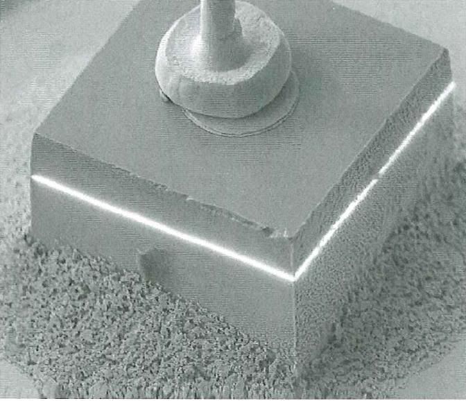
i'm not sure what your day gig is (i know you're pretty sharp as i've read several of your posts), but here's what an IR LED looks like while under bias. it's an EBIC image taken as part of a failure analysis i did (the white line is the P-N junction):
 

scsinet

Active Member
Originally Posted by saxman
http:///forum/post/3187268
as for semiconductor physics, i deal with that on daily basis
I figured you did - was only trying to throw a bit more information out there for folks who might think that wiring LEDs in parallel was just like wiring incandescent lamps in parallel. No knock on you.

ah...i guess i need to stop multi-tasking. what stuck in my head was "...my moonlights in my 24gal Aquapod crapped out on me." and "I want to add two blue(470nm) LED's and two UV(361nm) LED's to my hood on two separate circuits with separate switches to be able to control them individually."
Ahh... you're right, he did say that. I was going by the "15*" and "30*" that were listed by each LED, as that was all of the post I could fit on the screen while I was pecking out a reply... hmmm... well depending on what the OP really meant, this whole conversation may have been a moot point. If all he is doing is 4 LEDs, he can just use individual resistors and be done with it.
 
S

saxman

Guest
i think the 15* and 30* are beam emission angles. it sux not to be able to type symbols...
 

asharp13

Member
Originally Posted by SCSInet
http:///forum/post/3186934
I'm going to derate by about 20% because likely, the LEDs will not last long being driven at these values, as these are "absolute maximum ratings."
I am also assumuing a 12 volt power supply
For a single LED:
Blue LED: 25ma current @ 3.6v fv = 330 ohm, 1 watt resistor.
UV LED: 25ma current @ 3.8v fv = Same thing.
However, if I'm reading this correctly you want to use 30 blue and 15 UV LEDs... so... I'd connect them in series-parallel to reduce the resistor count and increase efficiency. You should be able to do 3 in series...
Blue LEDs: 3 in series, 25ma, 3.6fv = 48 ohm, 1/2 watt resistor
UV LEDs: 3 in series, 25ma, 3.8fv = 24 ohm, 1/2 watt resistor
So what you'd have to do here is assemble (10) groups of (3) series connected LED/resistor, and then wire the 10 groups in parallel. Then you'd do (15) groups of (3) for the UV.
Alternatively, you could do groups of 5 with a larger supply. If you could get a 24 volt supply, you could do (6) groups of (5) with a 240 ohm, 1 watt resistor, and (3) groups of (5) UV LEDs with a 220 ohm, 1 watt resistor.
Ohe word of caution... your LEDs don't seem that powerful. The current figures lead me to believe that these LEDs are pretty weak. What you should be looking at are the Luxeon or Cree 1w or 3w LEDs. They are mounted on a little aluminum heatsink substrate, and you can get optics for them that will focus the light down into the tank. Also, UV LEDs typically do not emit visible light.
12v assumption is correct
the 15* and 30* are the degree values of the LED's!!! not the quantity hahaha i want one circuit with 2 UV and a separate circuit with 2 BLUE both connected to the same power supply but with independent switches so i can control both of them individually.
i may do 4 of each if you think they arent powerful enough that is always an option. i am really tryin to understand the thinking behind the process and not the actual design so i can build my knowledge on the subject. i want to gain enough knowledge so i can put together a step by step tutorial fo future reefers
 

asharp13

Member
i was thinking of doing that for both sets, attaching a swith between power supply and the resistor, and soddering both seperate circuits to the single power supply outlet. do i have the right idea?
how do i figure out what to set the supply voltage to? what resistor i need on each circuit track? and i think thats it right?
can you guys help me understand the thinking behind all this. and can you walk me through the set up with each circuit having 2LED's and 4LED's? i want to jimmy rig the system with 2 originally so i can teach myself the process and see the strength on the LED's. then if it is not enough, add 2 more (totaling 4 on each separate circuit for a grand total of 8). remeber i ony have a 24gal that is about 20" deep and originally had 2 Blue LED moons that i thought were sufficient.
 

scsinet

Active Member
What you pictured is a series circuit.
Egg on my face about the beam angles. with (2/2) or (4/4) you could easily do individual resistors on each LED, or parallel them. You could also series them almost exactly as pictured, but (4) in series will not work on 12 volts.
First, for the power supply, try Goodwill. They usually have a basket of misc. power supplies for a buck or so each. You may be able to find one in the 16 volt at 1 amp (1000ma) range, that will power (4) in series if you wanted to go that route. You'll definitely find a 12 volt one for a ton less than Radio Shaft sells them for. For (8) of the spec'd LEDs, you could use a 500ma supply with no problem.
The switch arrangement you talked about sounds about right. I drew up a quickie diagram. I used the series-parallel arrangement I talked about only because you can easily see how you can add more LEDs to each switch or remove them, 2 at a time, so it'll work for (2) or (4) LEDs per circuit. In this case, a 180 ohm, 1 watt resistor would be what I'd use for each resistor shown in the circuit.
One other idea... you might consider actually using two different power supplies. This way you could plug each one into timers and automate the lighting.
 

asharp13

Member
great thanks for the help!! that diagram is exactly what i was looking for. i want to do 1 power supply cuz the BLUE LED's will be left on all day and the UV's just for a couple minutes at a time just for effect.
how do u calculate the resisotor? do u use a website or something? what values do i plug in? and how do factor in the multiple sections and multiple resistors? does that 12v get to each resistor? and each section is calculated separately?
should i set my power supply to 12v then?
and after the resistor, do i connect one (+) lead from LED(A) to a (-) lead on the second LED(B)? seems not right but that is how it appears so im just making sure.
whats the max # of LED's i could run off of the 12v 1A power supply?
 
S

saxman

Guest
Originally Posted by asharp13
http:///forum/post/3187292
is this a parellel circuit?
that would be a series circuit. in a series ckt, the current is constant, but the voltage across each component will vary depending on the resistance of the component.
in a parallel circuit, the voltage is constant, but the current varies depending on the resistance of each "leg" of the ckt. to connect LED's in parallel, you'll have a positive bus and a negative bus with one lead of each LED connected to one power bus (wire), and the other lead connected to one lead of the resistor and the other lead of the resistor connected to the other power bus (see bad dwg...i suck at paint!)
the reason i like to use parallel ckts is because all i have to worry about is the current in each leg, which can be dealt with using the limiting resistors. in this case, each leg will be the same, so the current will be equally divided among each LED.
also, if a LED fails in an electrically open mode, the other LED's will still function. in a series ckt, if an LED "opens up", you need to test each one to find the failed device.
 
S

saxman

Guest
here's a bad/quick dwg of the LED's in parallel:
circle = LED
rectangle = resistor
in this instance, you'd set your supply to 4.5V

SCSI: nice dwg! are you using a schematic pgm?
 

asharp13

Member
sax, im am beginning to understand this stuff...honestly its awesome but i firmly believe that the only stupid question is the one that you dont ask...so i have to ask:
why 4.5v? is it cuz the 3v setting is not enough to power the LED's and 4.5v is the next one up? and u want to pump at least 3.6/3.8v to that specific LED?
does it matter how many LED's you put in that diagram? will each one get that 4.5v being pumped out by the power supply? and is this asumption correct: you could use any power supply setting (4.5v-12v) as long as it is above the voltage required by the LED...the only difference in the circuit being the resistor that is needed to bring the supply voltage down to that which is required by the LED to operate efficiently.
 

scsinet

Active Member
Originally Posted by asharp13
http:///forum/post/3187313
how do u calculate the resisotor? do u use a website or something? what values do i plug in? and how do factor in the multiple sections and multiple resistors?
To caculate the value of a resistor for an LED, use the following forumla:
r = (SupplyVoltage - ForwardVoltageOfLED) / Desired LED Current
So... in the case of 12v supply, a 3.6v forward voltage, and 25ma of current,
r = (12 - 3.6) / 0.025
r = 8.4 / 0.025
r = 336 ohms. 330 ohms is the closest common value to this, so hence my earlier caculation of 330 ohms.
If you are using LEDs in series, you'll do the following:
r = (SupplyVoltage - (ForwardVoltageOfOneLED * NumOfLeds)) / Desired LED Current
r = (12 - (3.6 * 2)) / 0.025
r = (12 - 7.2) / 0.025
r = 4.8 / 0.025
r = 192
Again, here I went to the closest common value, 180 ohms, which will push the current up slightly, but still well below the 30ma maximum rating.
For LEDs in parallel, you'd do this:
r = (SupplyVoltage - ForwardVoltageofOneLED) / (CurrentOfOneLED * NumberOfLeds)
does that 12v get to each resistor? and each section is calculated separately?
In my diagram, each string of (2) LEDs and one resistor get calculated together.
should i set my power supply to 12v then?
My calculations were based on a 12 volt supply voltage. Apply the above forumula to adjust for different supply voltages.
Bascially, your supply voltage has to be greater than the forward voltage of the LED. In the case of series connected LEDs, the power supply must be greater than (NumberOfLeds * ForwardVoltageOfOneLED). The higher the margin over the required voltage, the larger your resistor. So if you have one LED needing 3.6v, you do not need a 12 volt supply, a 4.5v supply will do, and require a smaller resistor of a lower wattage rating. However, (2) 3.6v LEDs in series will require the 9v setting minimum.
and after the resistor, do i connect one (+) lead from LED(A) to a (-) lead on the second LED(B)? seems not right but that is how it appears so im just making sure.
Yes. When doing series circuits, the positive from one LED connects to the negative of the next, and so on.
whats the max # of LED's i could run off of the 12v 1A power supply?
It depends entirely on your circuit configuration. By using series-parallel, you should be able to run more than 90. In parallel, you'll be able to run no more than maybe 30.
 
Top