Algae Scrubber design help

cipher43

Member
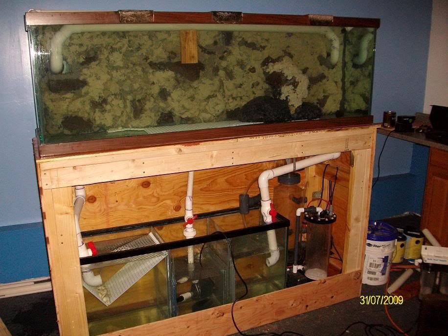
So I am in need of all of your help here. I am planning on putting a scrubber on my new tank (120g+40G sump) and my moms tank (55G+20g sump) after I finish the stands for the 2. So for my moms tank I plan on using a 6"X 12" screen and my tank i am planning on using an 12"X14" ish screen for mine.
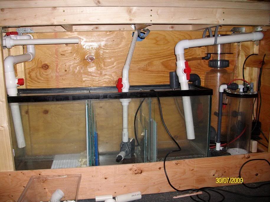
So the first question is how many GPH do i need for each of the scrubbers. Right now her tank has a return that puts out 550 GPH or under after headloss in her tank. I do plan on putting the return pump off of my 30 gallon on her tank aswell when i upgrade so she will have two returns for more umph cause her tank always has a layer of stuff on the top of the water. will that be enough for her scrubber or will i need to use a different pump? As for my tank i plan on getting a pump that will give me around 900GPH after head loss. As of right now i do plan to avoid adding another pump to the systems and just using the overflows on each.
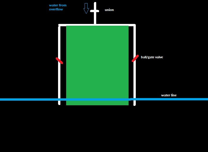
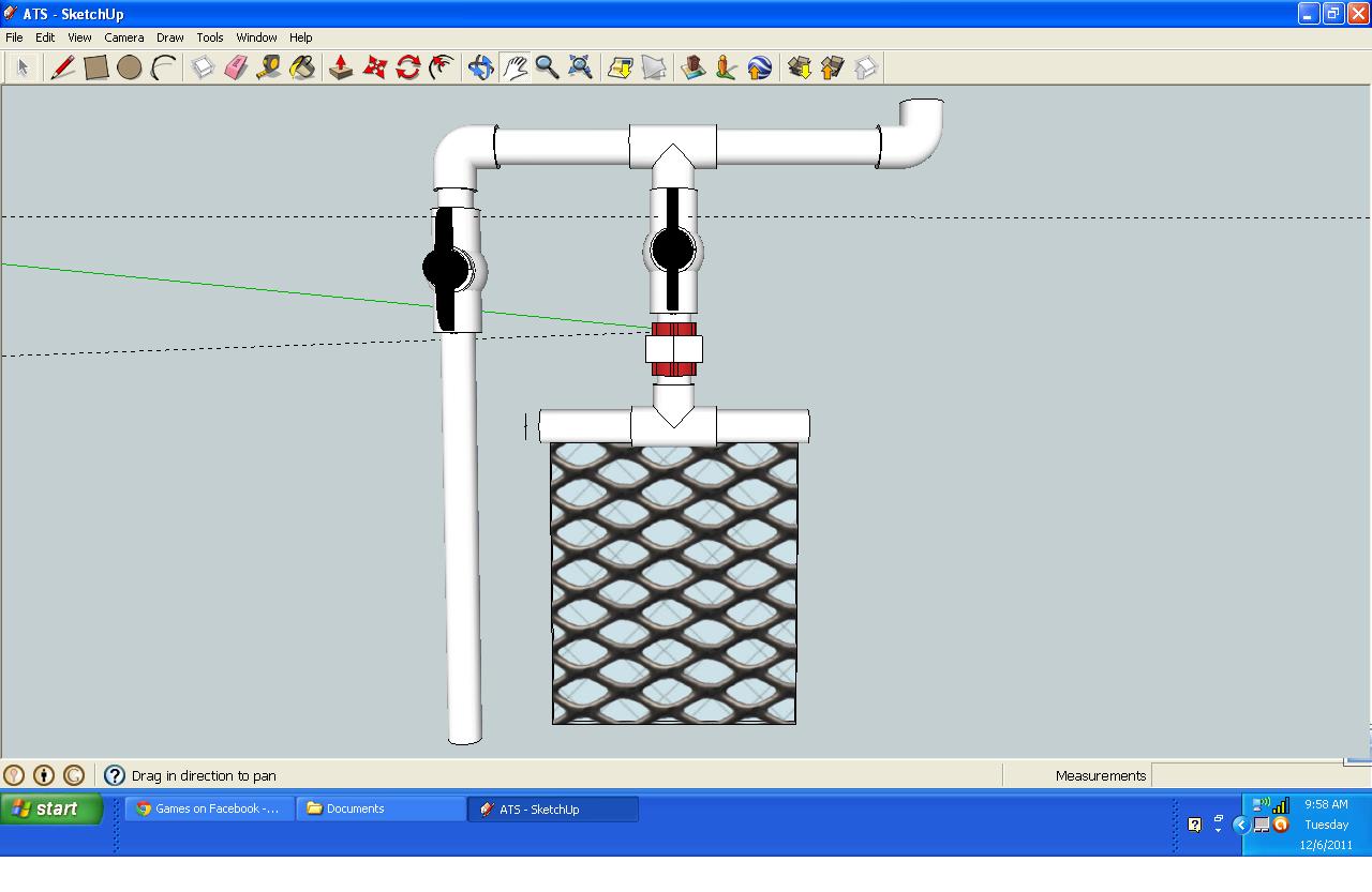
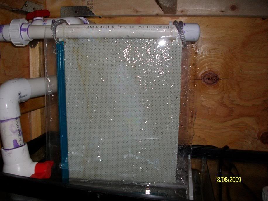
Second question is about design. I have been trying to think about a good way of doing it and I think i have it narrowed down now so i wanted all of your opinions.

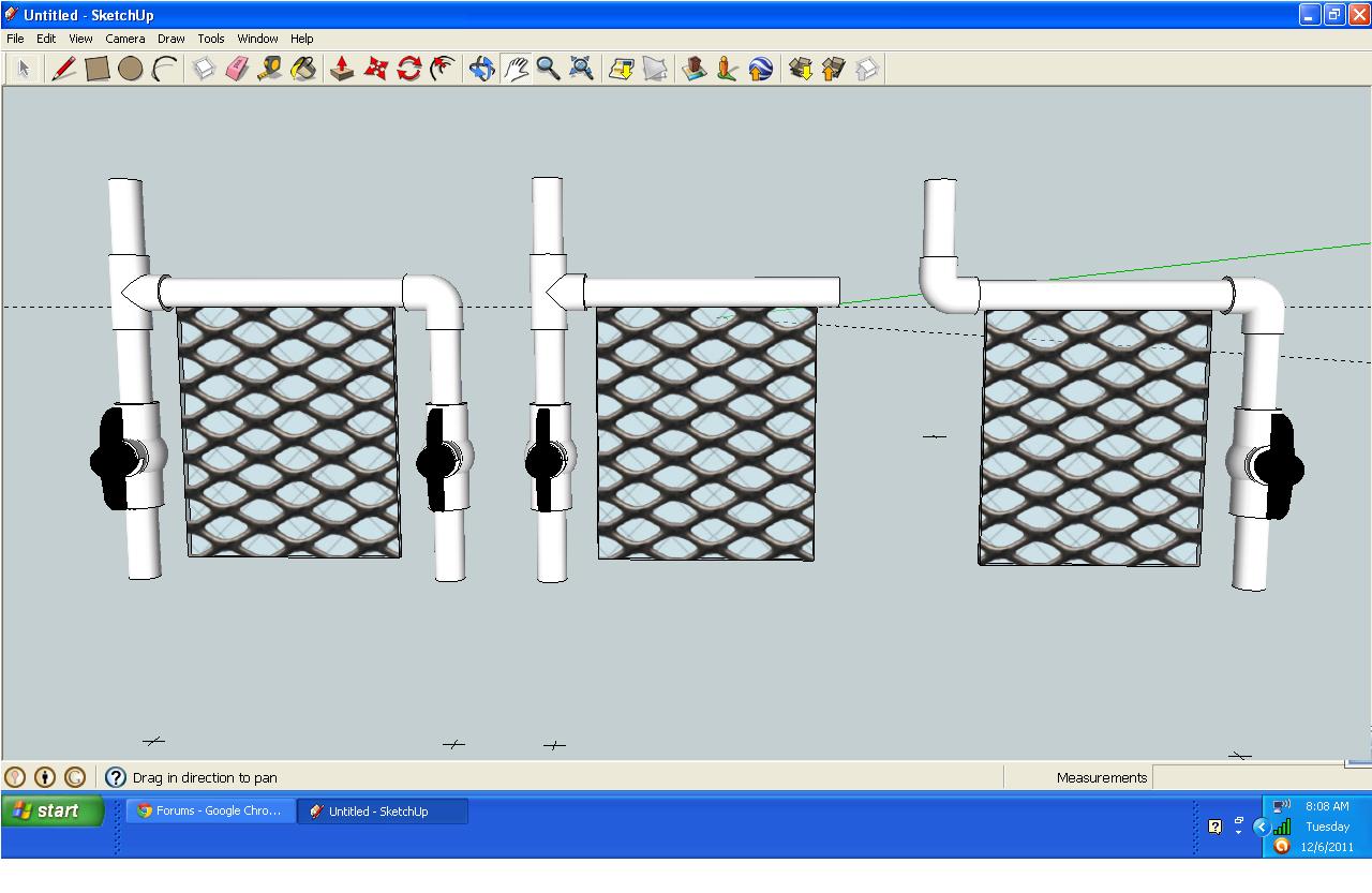
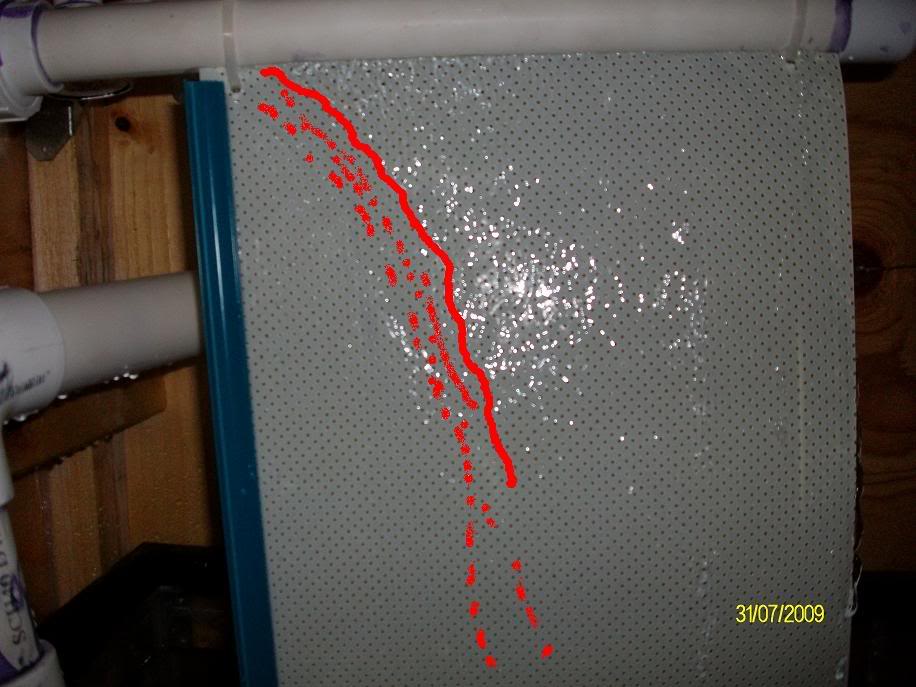
At the moment i am thinking of ding the one thats on the far left because i would be able to adjust the flow and still have the water flow through when the ATS is removed. I couldnt find a union that would work on google sketchup but i do plan on having a union off of the T to remove the ATS.
So what do you guys think?
 

cipher43

Member
Also i plan on posting a pic of her tank and her algae problem she has right now once we get the tank moved to the new stand and the ATS on it to show progress. Im thinking its going to be a great demonstration of what a scrubber can do cause her algae is really bad right now.
 

snakeblitz33

Well-Known Member
I also like the one on the far left. However, instead of ball valves, I would go with gate valves. They are more precise. You will probably find that the ball/gate valve on the farthest left will almost be entirely closed at all times, but it would allow for better adjustment.
The gph over the screen depends on the horizontal width of the screen. you need 35gph per inch of horizontal length.
I also have another idea for the design, and I'm just putting it out there for consideration...
You could put a T fitting in the center of the scrubber that is fed by your overflow, and have both ends of the scrubber fit with ball valves. At the top, you could use a union. It would allow for more even flow across the screen. The only problem I see is taking the scrubber off to be cleaned, you would have to turn your return pump off or replace it with a piece of PVC with a union on it while you are cleaning the screen.
Just another design to consider.
Also, think about a splash shield and how you would mount it. Personally, I am going to install a scrubber into a drilled 10g aquarium , and baffle the inside of it and install the lights in the dry spots... Kind of like Al&Burks design.
 

snakeblitz33

Well-Known Member
It definitely will. I love these kinds of threads that show the power of scrubbers. :D Can't wait for more pics. I'll post a "paint" pic of the design I am talking about soon.
 

snakeblitz33

Well-Known Member

Simple, basic design. It would allow even water flow over the screen (if the slot is cut correctly, all the way across the T) and the ball valves on the sides would simply be a way for extra water to escape, if there was too much flow over the screen, or if you wanted to increase the flow over the screen. As you see, the union at the top can have another piece of pipe with the other side of the union on it that you can replace the screen with to keep your return pump going when you are cleaning the screen.
Anyways, I'm not saying DO THIS DESIGN, I'm just saying consider it, and if it suits your fancy, give it a go.
 

cipher43

Member
oh i like that one. Makes me think of a way to modify the ones i made in sketchup so i will try and fix them and repost and see what you think of it.
 

cipher43

Member
ok here was the thought i had off of your design.

Would bypass the problems i think but let me know. Also i know i have it designed with a T then ball valve and then union but i wonder if i could use a Y and then a 45 to make it straight up and down so the water would be morelikely to go into the scrubber and have the rest overflow to the left side where it would bypass. Also it would make it when i remove the scrubber i could leave the pumps on and open the ball valve all the way. I shouldnt have a problem with height under stand being her stand is going to be tall and my stand is really tall lol. What do ya think Seth?
 

cipher43

Member
Found the 45 degree and Y i was looking for so here is what i meant Seth

That way the water would willingly go down into the scrubber and only go out the left tube if the valve was flipped or there was too much flow. What do ya think?
 

king_neptune

Active Member
900gph turnover on a 20g? Just making sure your not doing a fuge down there as well. Cause that's really fast if you plan to have stuff growing down below.
My water runs really slow over my current fuge. Right now my 55g fuge has about 160gph turnover. Its nice and slow so things can stew a bit.
Back on topic, here is an old scubber I did a couple years ago:


Its pretty self explanatory. It was double sided and had about 300gph running across a 10.5' wide screen. It was the drainage from the overflow on a 125g tank.

The sump in the photo was a 55g that I picked up for $20 on CL. I had the return in the middle. The overflow from the DT could go down the right or left side, I could independently control more or less flow to each side depending on my preference. EX: the scrubber side had just LR in it. The other side had a fuge going where I could really slow it down significantly if I wanted. The return I could also throttle as needed:

At first the water didnt flow good, but after algae grew things were fine:


Hope this helps.
 

cipher43

Member
Quote:
Originally Posted by SnakeBlitz33 http:///t/389332/algae-scrubber-design-help#post_3440365
I like Al's design. No offense. Lol.
None taken. I like his too lol
Quote:
Originally Posted by King_Neptune
http:///t/389332/algae-scrubber-design-help#post_3440367
900gph turnover on a 20g?
the 900 GPH is going on my 120 with a 40 gallon sump/fuge. Also the tank has double overflows so i may put one going into the fuge and the other one feeding the ATS.
Like your scrubber btw
What size pipe would you all suggest for these?
 

king_neptune

Active Member
Quote:
Originally Posted by Al&Burke http:///t/389332/algae-scrubber-design-help#post_3440371
Nice Scrubber - I don't understand this part
Water from the DT drains down to the "T" and can go two ways: to the line down below, or keeps moving forward to the upper line. I could close off the bottom line and force the pressure to the upper line, or vice versa cut the upper line and have it flow downward. The upper line was what fed the Scrubber. I honestly only opened up the bottom line when I was needing to clean the scrubber. In that case I would close the upper butterfly valve and open the lower one. From there I could unscrew the scrubber via a simple coupler.
 

king_neptune

Active Member
Quote:
Originally Posted by Cipher43 http:///t/389332/algae-scrubber-design-help#post_3440373
the 900 GPH is going on my 120 with a 40 gallon sump/fuge. Also the tank has double overflows so i may put one going into the fuge and the other one feeding the ATS.
Like your scrubber btw
What size pipe would you all suggest for these?
Your fuge side doesnt need much, youlle just have to make a judgement call really. Remember, think of it like the crockpot of the tank. Its just not cool to have water racing though a fuge.
If memory serves me, my main drain line on that build was 2" each side. And my scubber junction featured a 1.5" offshoot. Theres plenty of gravity calculators out there. I think I chose to have overkill on each side so that in emergancy, one whole side could get backed up(which never happened) and still have enough to allow drainage on the other.
 

cipher43

Member
So im going to buy the stuff for both my parents and my ATS and overflows pipping this week. My ATS is going to be like the one AL designed. I have a question on the design for their ATS. When i built the stand for her 55 gallon I made it big enough to hold a 75 gallon tank for main display. For the under stand part I made it big enough for a 20 gallon tank with plenty of room for an ATS above it. Thing is for Christmas they got a 75 so instead of keeping the thought of a 20 gallon sump/fuge we stepped it up to a 40 gallon for the extra room. I still have room under the stand just not as much for the original design so things may need to change.
What i thought about doingi s drill a hole in the stands top board and put the line though the hole so i can keep the same design. Will that make the top rails weak or will it still be good. The stands top is 2X6 boards and the hole would be big enough for a 1 1/2 " pipe.
Will that be safe or should i just change the design completely?
Im leaning toward changing the design and can give you some dimensions when i get back to the house to give you a better thought of the space i have to work with.
 

snakeblitz33

Well-Known Member
Draw up a design in paint program and we can spot flaws in the design. It's hard to visualize it with just words for me.
 
Top