Ciphers DIY 120 and 75 gallon LED build

2quills

Well-Known Member
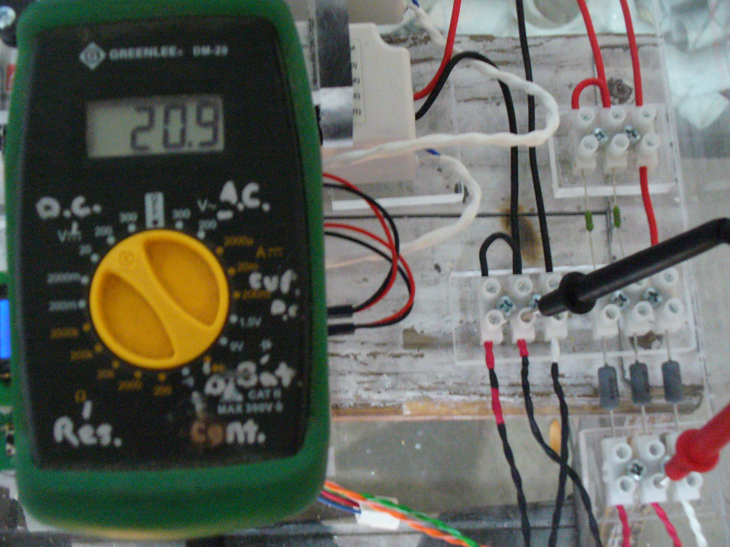
Here ya go, Greg. This is how I do the total voltage test across a whole string. Red probe on positive side of red string #1 at the beginning and black probe on negative side of red string #1 at the end.
With my red leds running at low power (8%) I get 20.9 volts for my forward voltage on that string. That's when they first kick on. When I run them at 100% I'm pulling about 32 volts. That's why I chose a 36v driver to run the reds...it operates between 21-36 volts (just fyi).
Meter set at 200 dcv

My fuses don't blow nor does amperage increase.
 

2quills

Well-Known Member
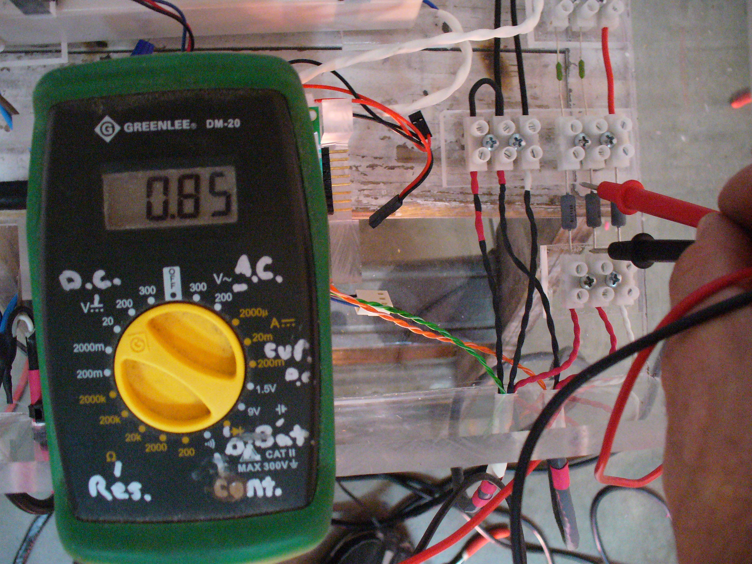
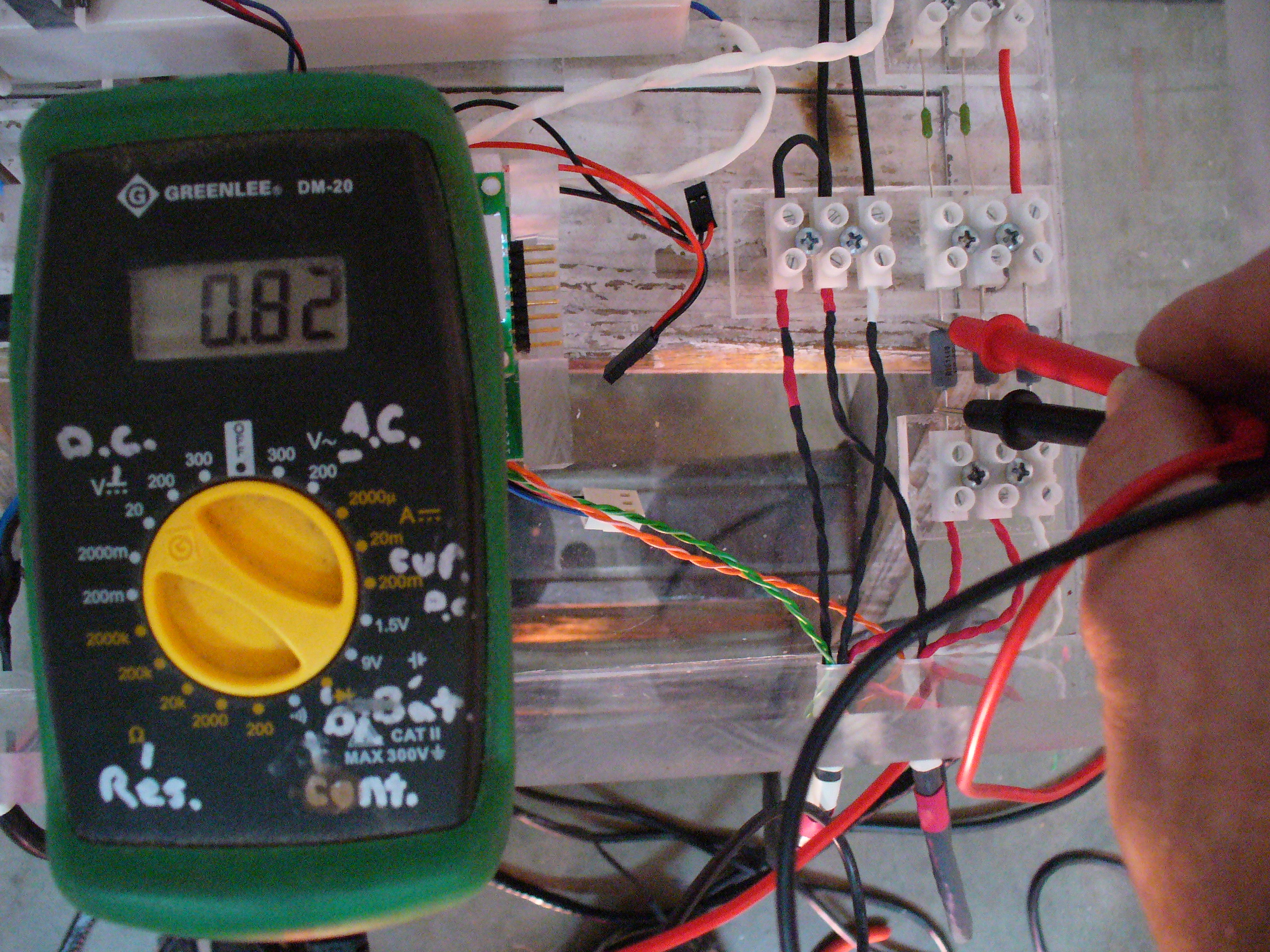
Here's the voltage drop test across the resistors on my red strings.
According the the power rating on my driver it's supposed to put out a maximum of 1.67 Amps.
Red String # 1 at 100% I get 0.85 volts (850mA)

Red String #2 at 100% I get 0,82 volts (820mA)

0.82 + 0.85 = 1.67 Amps. So my tests seem to be jiving perfectly with what data sheet and driver claims it can do. It's the same way with my white driver. And the fact that I'm only seeing a 30mA difference between my two red strings means they are close enough that I don't have to worry about balancing for now. Anything under 50mA and you're doing pretty good.
 

cipher43

Member
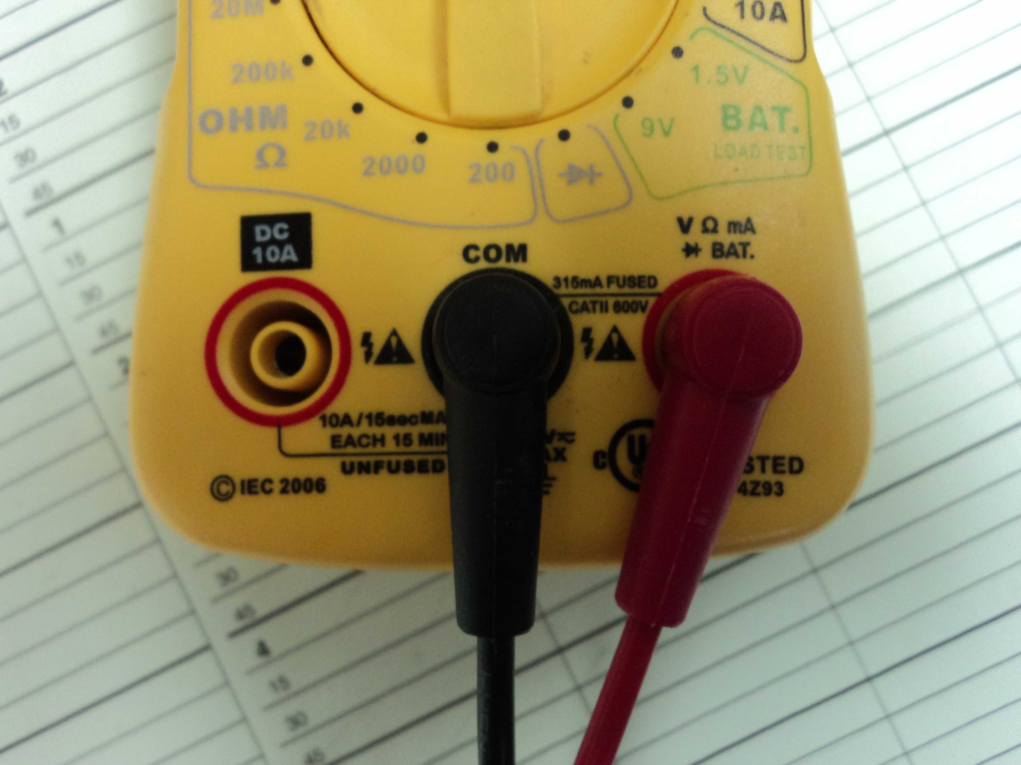
WOW do you ever have one of those moments where you feel like a complete idiot? Cause I just had one of those moments. On my meter it has 2 different places to plug the positive plug, one for DC 10A and the other one for V, ohms, mA, and battery............ I had moved it to the DC 10A side thinking it did all DC current..............

Now im getting the readings I should. All the strings I have are exactly balanced together so it looks like all I need to hook up are my red/green strings and if those are balanced this light will be hung today!!!!!!!
Moral to the story is check that you have the plug in right so you dont stay up most of the night wondering what the heck you did wrong LOL
 

2quills

Well-Known Member
Ahhh. That makes a little more sense. I don't have to move the probe on any of my meters to do the d.c. current option that's probably why it didn't register with me. Well, you had it half right in the sense that that's where you would have wanted to have the probe to do an actual current test. But seeing as how we're using resistors in our cases we can simply do the voltage drop test across the resistors to give us a reading in volts that is the same conversion of Amps. It's just a lot more convenient then having to break open strings and hook your meter up in-line with a led string to get an actual amperage reading. Glad ya got it figured out and it's something to remember.
 

cipher43

Member
Ok so I got the whole light hung in the topper and put it up and now I dont have one of my blue strings working. I checked my fuses with the ohm meter and it is good so I dont know why one stopped working now. any ideas?
 

cipher43

Member
I just pulled that sides light out and tested each led and they all lit up so more questions arise for me now
 

cipher43

Member
yes i did but Im starting to think it was just bypassing the bad one, Im working on a theory at the moment
 

cipher43

Member
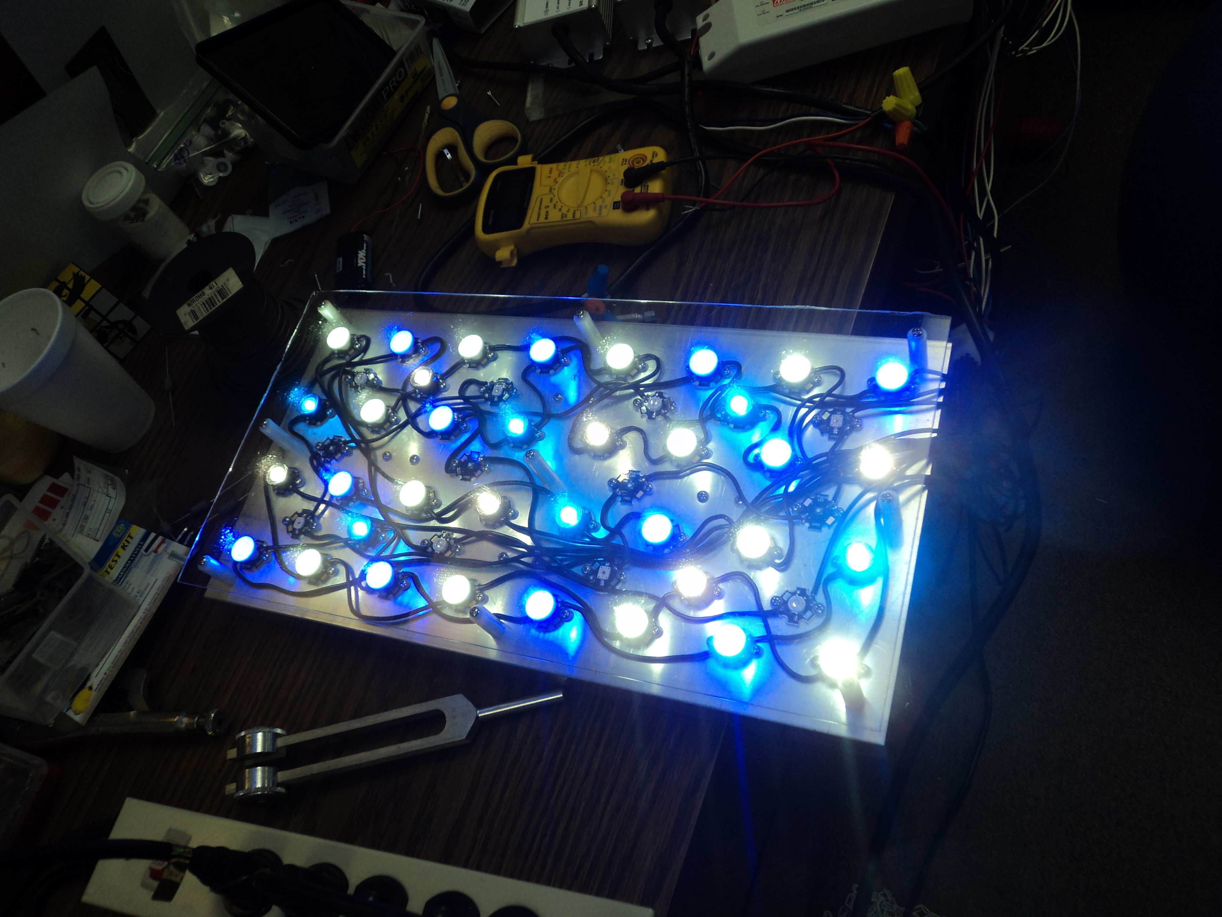
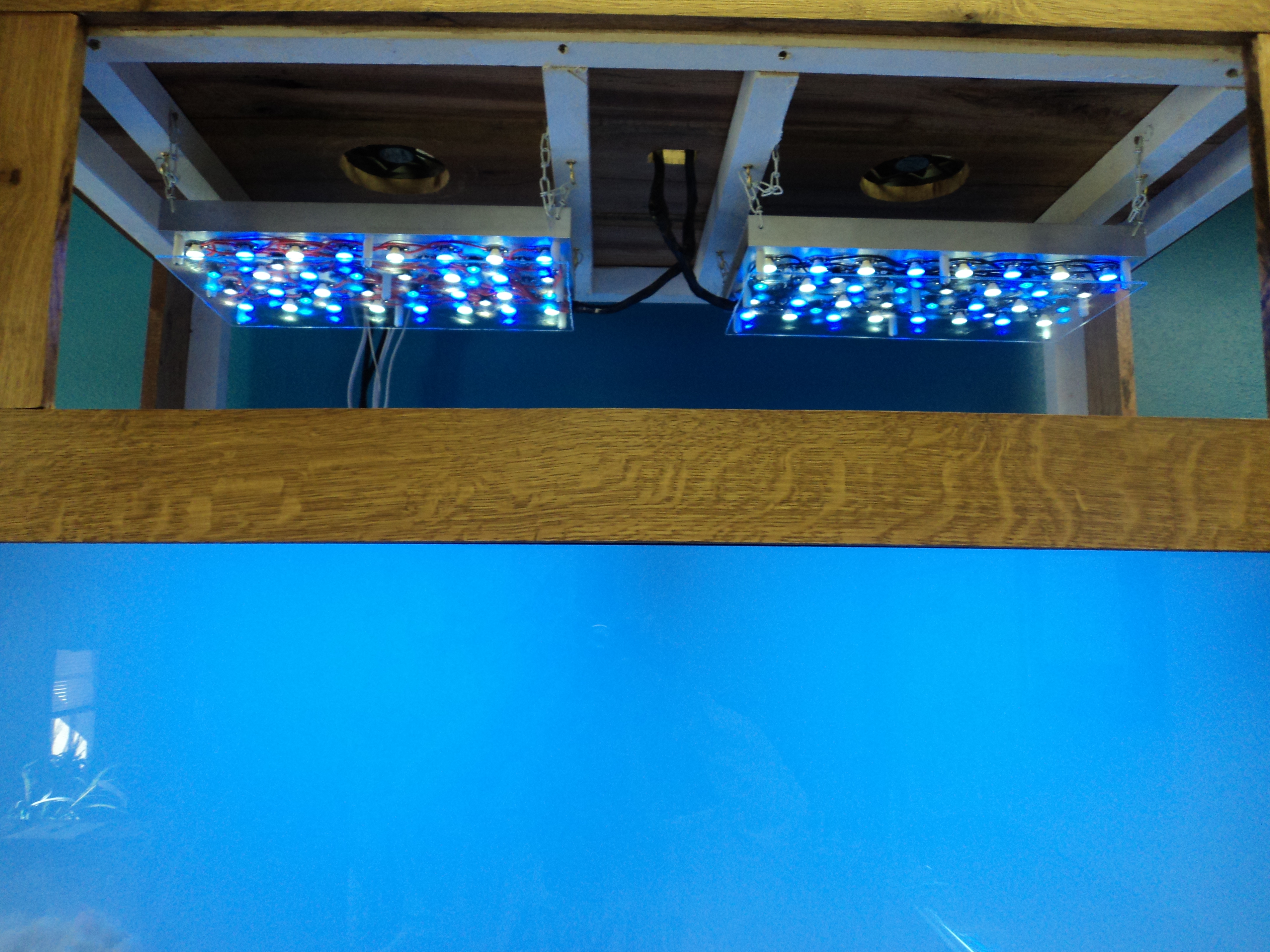
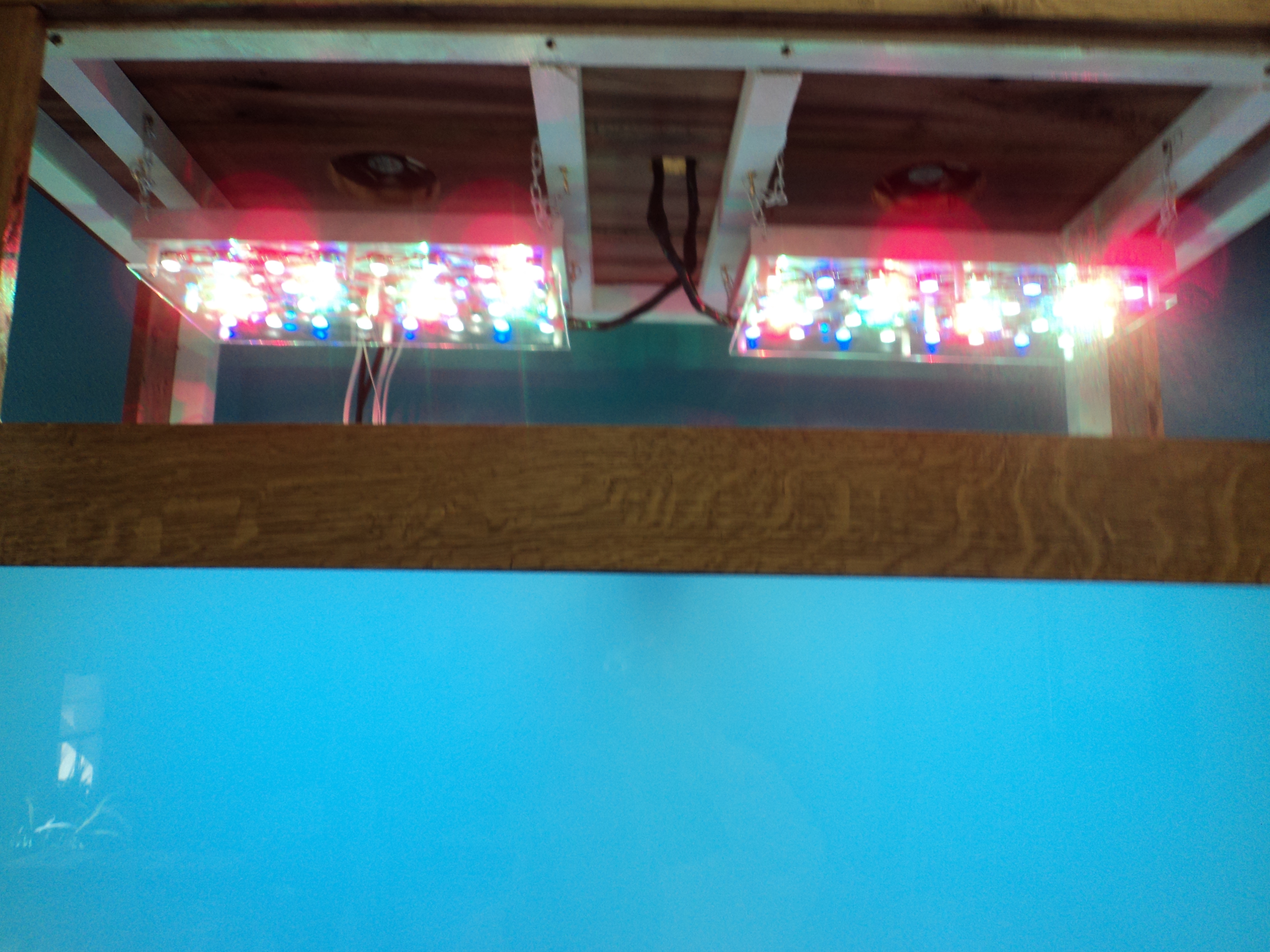
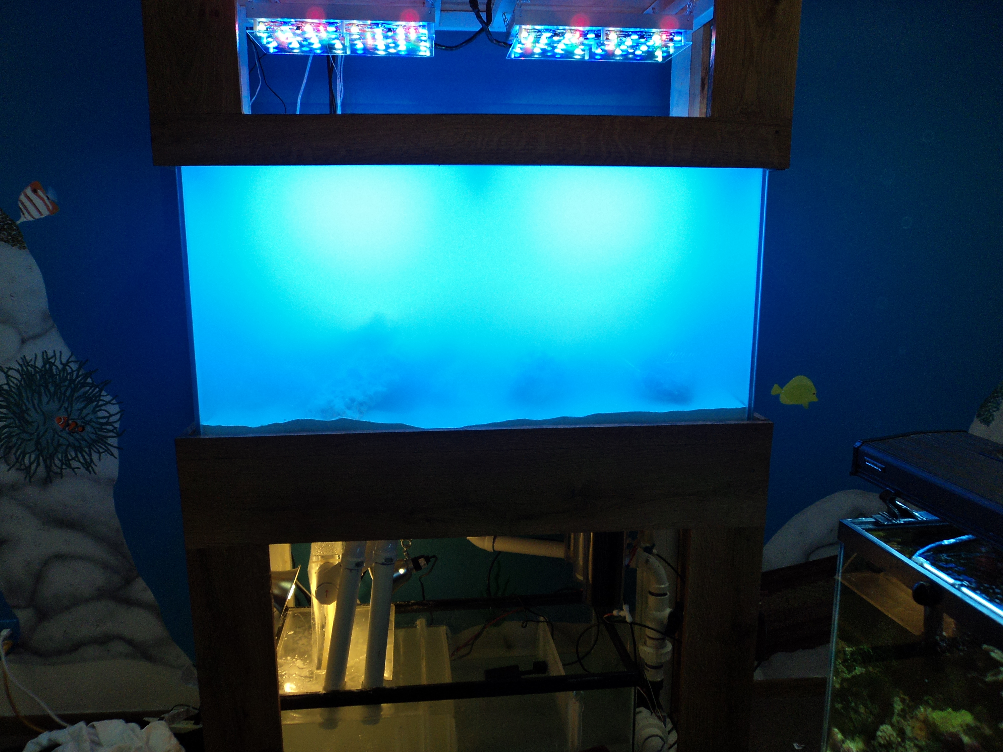
so here are some of the pics we took during the setup

here is with all of the lights set to 750 mA

here are the blue and white on the lowest power I can go

the blues and whites on lowest power and red and greens on 750mA

and finally a look full view of the tank with all lights on 750 mA

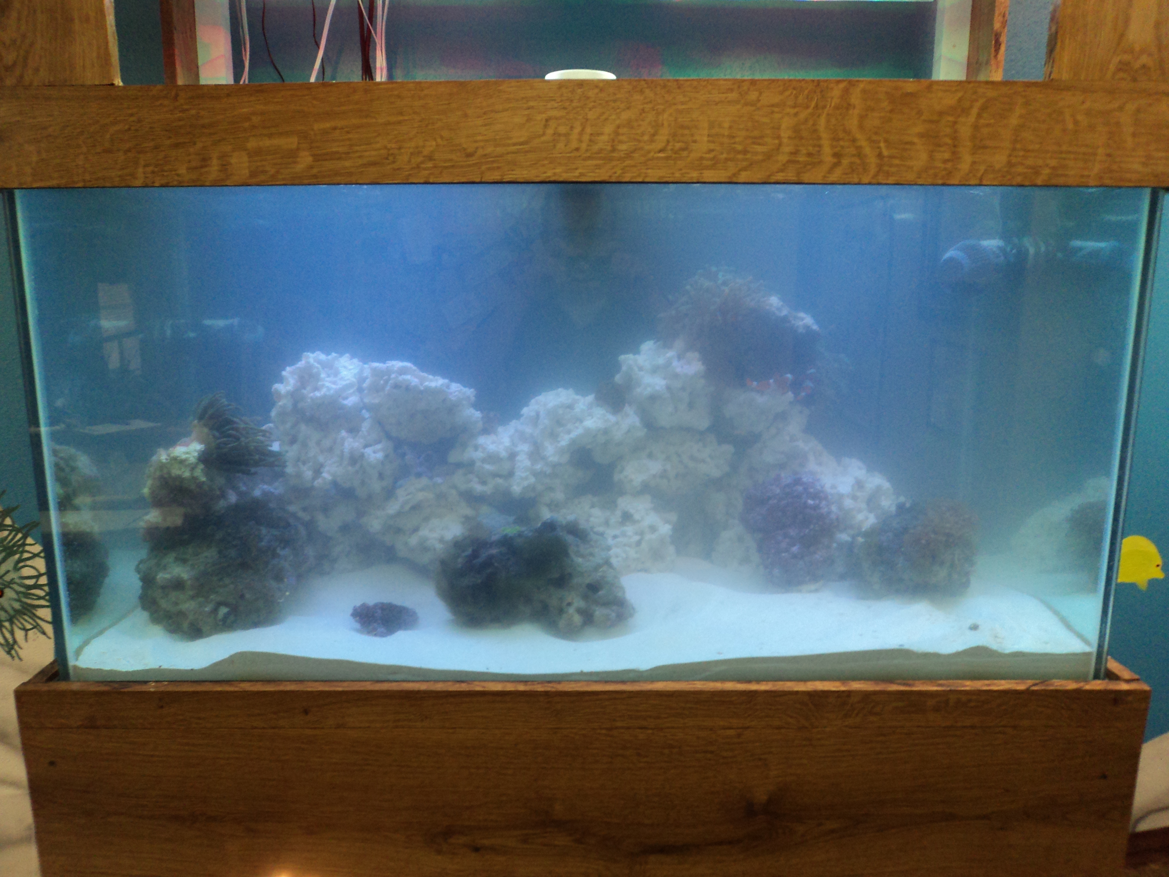
I will get a full view of the tank after the dust settles and post it most likely tomorrow. I can already tell the colors are gonna be awesome because the light that escapes the tank and hits the 30 gallon is making the anemone tentacles and our corals pop.
 

2quills

Well-Known Member
Wow, can't wait to see once you get that thing tuned in with some livestock in the tank. Looks great!
 

cipher43

Member
So after 5 hours this morning between patients I got everything switched over to the new tank so after it clears up alittle more from the rocks I will post a pic of the final product. I really love the color mixes we have and wouldnt change any of that although I do have one regret. And that is that i went with the HLG drivers and not the ELN drivers. Im actually at the point where I am debating on buying the ELNs and either selling the HLGs or keep them for a later project depending on what I can do.
 

cipher43

Member
Quote:
Originally Posted by 2Quills http:///t/390510/ciphers-diy-120-and-75-gallon-led-build/60#post_3464817
Whats the issue with the hlg's?
Main complaint I have is I can't use the typhoon controller or arduino to run the sunrise and set. Still not sure on the dimm4 and if its a good unit. The good part about the drivers is I have plenty of head room for how much i can turn them up cause I only have them at 1/2 to 3/4 of the way up and they are set to 850mA. BTW what would you suggest setting the lights to now that all the bugs are worked out. 850 mA good or should I go higher?
 

2quills

Well-Known Member
Quote:
Originally Posted by Cipher43 http:///t/390510/ciphers-diy-120-and-75-gallon-led-build/60#post_3464837
Main complaint I have is I can't use the typhoon controller or arduino to run the sunrise and set. Still not sure on the dimm4 and if its a good unit. The good part about the drivers is I have plenty of head room for how much i can turn them up cause I only have them at 1/2 to 3/4 of the way up and they are set to 850mA. BTW what would you suggest setting the lights to now that all the bugs are worked out. 850 mA good or should I go higher?
Honestly, I've looked around and couldn't find any bad reviews on the Dim4. They're pretty much the same thing, both are bare bones pcb's with, chips, capacitors and resistors just like the Typhon. I'm pretty sure all the Dim4 is doing is simply filtering 5 volt pwm output essentially smoothing out the modulated wave form of the signal thus converting it to analog signal and then amplifying it to get the 10v.
I wouldn't rule out ALL of the other PWM controllers out there. The issue that myself and a couple others have seen are with the Typhon. And the reason being is the way that the Typhon was designed and how hardware was used to create the 10v channels. When the guy originally designed it what he did was simply take the 5 volt pwm capabilities of the Arduino and amplified them by created a floating circuit using capacitors and transistors directly off of the Typhons AVR chip. This floating signal is called so because it's not grounded. This is specific to the Typhon. The Typhon's creator thinks this signal that is not grounded is what is causing the issue with the Meanwell drivers not being able to interpret it properly. The drivers dimming circuit, if it's OPEN or the wires are not connected to anything the drivers will run at 100%. And that's what our drivers are doing when connected to the Typhons 10v channels. The drivers simply run 100% as if there is no resistance.
But the Typhons 5 volts pins (channels) are grounded and the Meanwells will work just fine on the 5 volts pwm channels.
So I'd think you're safe if you wanted to use another PWM controller or build your own Arduino controller to either run analog signal or amplify the arduino's 5v pwm signal another way (with an OPAMP), perhaps. I'm still trying to work out a way to take the Typhon and amplify the 5 volt channels to 10 volt. I know there's a simple way but I'm still trying to work that out. It's on the back burner right now. I'm going to use the Typhon the way it is for now on my scrubber build because honestly I think I have too much light anyway. Probably won't need to go higher than 50% when I can put the lights within an inch or two of the scrubber if I want.
With the lights I'd start low (maybe 350mA'ish) and go from there. When ever you add a new coral try to be mindful of where it's coming from and what type of lighting it's been growing under. Adjustments to spectrum and intensity should always be a gradual acclimation whenever possible. Less stress the better. Good thing is you have a pretty full spectrum fixture going there so that's going to help make things easier I'd hope.
 

cipher43

Member
Yeah I may try the Dim4 or arduino build some day but we will see. If he gets the typhoon/hydra fixed I will probably do that build. I do have a typhoon here for the 75 build so I may try the 5v on my build and see how much power I actually get cause on my pot I only have it turned up about 50% when the power is at 850mA. One question though, when the signal from the typhoon first starts will it kick it on to full blast or will it start with low/no power and work up from there.
So far I have it set at its lowest setting which I cant remember what that is for sure but its lower than 350mA. .
Another question I have is do you have regular timers on your actual drivers or just the typhoon?
 
Top