CLS plumbing opinions please

saltn00b

Active Member
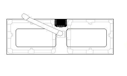
hi all. I will be getting my Sequence DART to push my CLS this week. the drain is already plumbed, and the Dart will be mounted on the underside of the tank on the left side. (upsidedown from the stand ceiling)
So now the question is, what is the best way to build the manifold?
here is the top of my acrylic custom 150g:
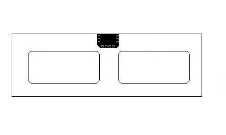
it has about a 3" lip around the top and then a rectangle cut out in the middle-back for the overflow column in black. i post this so it is easy for you to take the pic and draw your ideas on it and post up! think of it like a template

ok so i had two ideas
option 1:
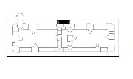
i think with this version it is possible the left side may get a lot more push than then the right. Although, the concept behind a manifold, where the PVC is built in a Ring formation, pressure stays even.
option 2:
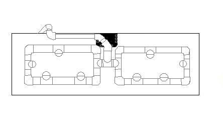
any input would be great!
sorry for double posting but this will be in my upgrade thread as well.
 
Well I am no pvc pro but I would thing to have that many outlets you would have to have a massive pump to have any sort of flow rate out of each head. With head loss and all the turns in the pipe I just don't know how much you could expect. My closed loop has a 1.25 outlet and two 3/4" inlets. I am using a 3000 gph pump and wish I had much more flow. I have been researching the ocean motions products thinking of adding another closed loop, just been trying to come up with a plan to not have to totally tear dow the tank. Anyway with the ocean motion you could have four outlets that would only fire one at a time giving you more pressure at the outflow and more random current due to the switching of outflows. Just an idea.
Rich
 

saltn00b

Active Member
OM can be built into it down the line, i just dont have the extra 500 or so to blow on it.
im using a DART which is 3600 GPH. the manifold will also keep pressure high. i may remove one of the outlets on each side and have a total of 6 outlets that are reduced to 3/4" 45 degree elbows.
 
The manifold will keep pressure up but it will add to the head pressusre reducing the flow of the pump. So 3600 might end up being like 2000 GPH +/-. Then when deviding the flow between the outlets you may or may not end up with a flow from each that you like. I think this is why mine does not give me what I want. My pipe is a little too small and that is what is causing my restriction.
Rich
 

saltn00b

Active Member
with a CLS you dont get head loss because it is countered by the gravity of the water pulling into the pump. you only lose a little bit of GPH with pipe friction. i expect to get to get not much less than the 3000 GPH out of a 3600 GPH pump.
 
Maybe, but I would think that only true if you line out of the tank is the same size or bigger than the intake on the pump itself. I think that is also one of my problems and wish mine was set up differently.
Rich
 
I meant to make sure you drill the holes for bulkheads matching the pipe sizes on the pump to get max flow. I think my pump has a 2" but The intake from the tank is only like 1 and a quarter so that restricts my flow greatly. Not trying to sound opinionated just trying to help you not make my mistakes because once its done its done.
Rich
 

isistius

Active Member
we drilled his tank when we moved it in december. if you read his tank upgrade thread, it details what we went through. appreciate the help tho.
 

saltn00b

Active Member
ok made some changes.
here is a more realistic view of the current tank, showing the Sump return locline come from out of the overflow column.

this slides out easily and so i am thinking of drilling the acrylic above where the loc line was and put the UNGLUED structure under it, secured by zipties through small holes.
 
Saltnoob,
did you get your cls up and running. Was wondering how your manifold turned out and if what you expected. Also what kind of strainer did you put on the drain from the tank. Was thinking about redoing my closed loop so I could move the drain and make it larger.
Rich
 
Top