Diy led

swimmer4uus

Member
Ok, sorry about the double post here.
Neptune, let's get your configuration down first. Hope you've have your coffee, cause this might be a long post. If at any point you have questions, please ask them as you don't want to go buy the wrong stuff.
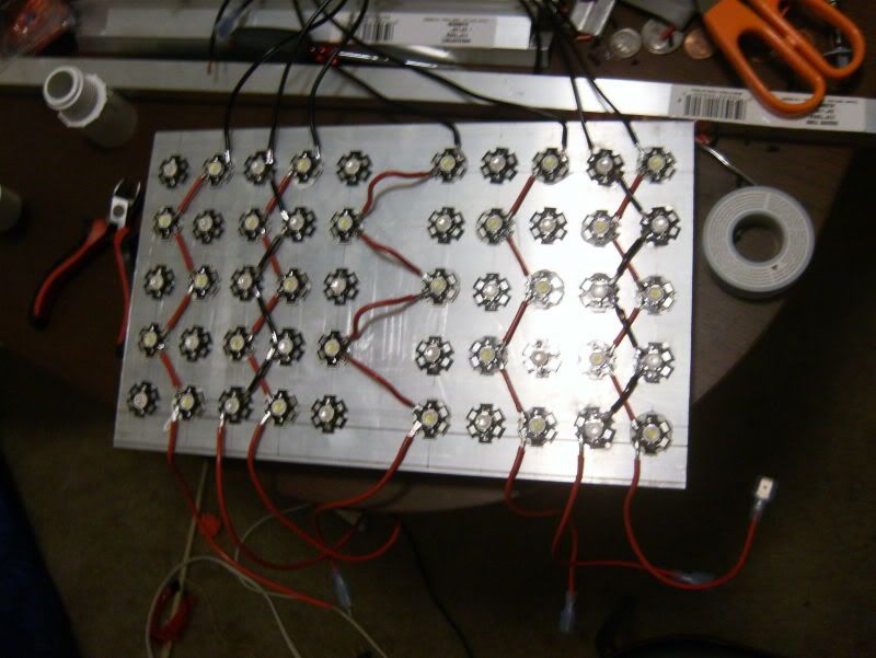
Yes you are correct. You're going to have 2 power supplies. I'll try to get some websites, and part numbers for you either later tonight, or tomorrow. I'll PM you with that info, and post this so anyone else reading can see this general info. Each power supply with be producing roughly 6.5 amps. I don't know how to put it nicely, but your calculations are not correct. Your power supply will provide 6.5 amps. You will spilt that up into 6 strings of LEDs, each string consisting of 5 LEDs if not for the driver. The drivers dictate exactly how much current will run through that string. So, for each string, 700mA will be flowing through that path, regardless of how many LEDs are on the string. 700mA times 6 strings is 4.2 amps. Theoretically you will only need your power supply to produce 4.2 amps. You will want the 6.5 amps just to have to some comfort room(details are more complicated than needed, maybe even run a fan. But you for sure don't want to add everything up and have your current draw equaling your max rating, as you don't want to run anything in this system at it's max rating. You do not add up currents when you are talking about a series. On the other hand, when you have 6 strings in parallel, that's when you add up the 700mA. We can talk about the different voltages when we design the drivers.
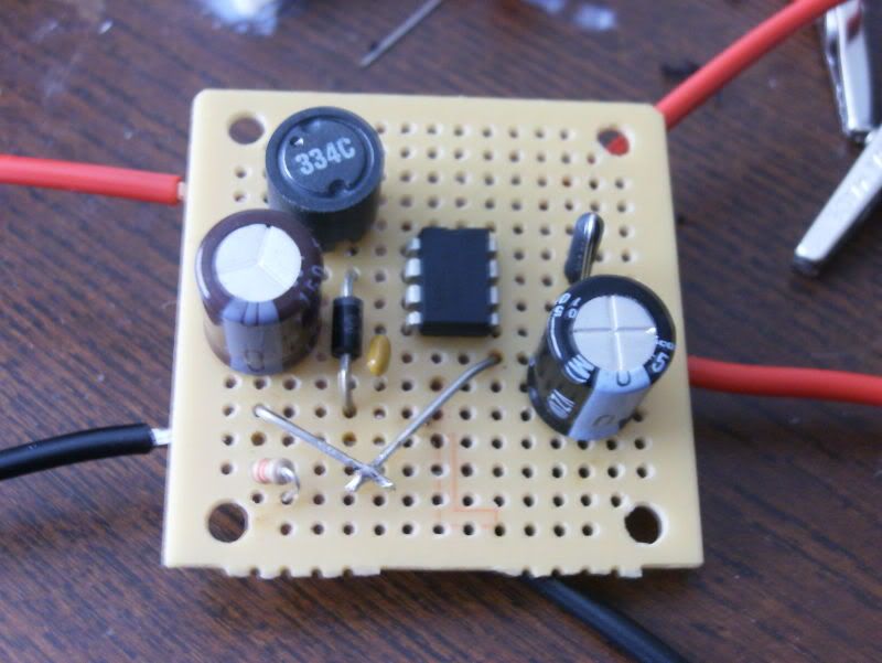
The driver will be another issue. You can use a bread board like I have been using for simple, prototyping a driver. If SCI and I can work on some things collectively, maybe we can produce a simple kit that could be put together without much worrying on your part. BUT, you'll have to wait for things to pan out there cause I myself aren't done with configurations and whatnot.
Some corrections to your last post. Having circuitry in parallel vs in series has no difference on the survivablility of the parts involved. It's a matter of circuit dynamics, and takes a lot of reading and/or a couple classes to get down. Part of my major required me to take Intro to Electrical Circuits at my school.
And lastly, I have yet to buy anything from the shack that is dirrectly related to my DIY build. Yes, I bought some parts from there to prototype some stuff, but in the end, nothing from the shack will be on my build other than a switch or two.
When are you planning on starting this build for your tank? I'll PM you with some links to the websites I've used.
 

king_neptune

Active Member
Originally Posted by swimmer4uus
http:///forum/post/3268121
Neptune, let's get your configuration down first. Hope you've have your coffee, cause this might be a long post.
I don't know how to put it nicely, but your calculations are not correct.
Some corrections to your last post. Having circuitry in parallel vs in series has no difference on the survivablility of the parts involved.
Just woke up. No cofee yet. Ill disect this more carefully in a couple hours.
No worries. I dont understand this stuff, I pretty much added it up, then divided by 1000. I thought thats how the math worked.
I pulled this off the big reef site:
"Series means the voltage is additive. Current stays the same. "
It comes from soundwavs build. Its now divided into three segments. since they are over 200 pages combined!
ALOT of info to disect, I found the series/parelell argument around page 20-30 on segment #1, but the quote came from thread #3, page 138 so its something that still gets brought up. In a nutshell, everytime it gets brought up, people smarter than me shoot it down. After a cocuple back and forths, Series comes out the winner, ALWAYS.
Ill try to dig them up later today.
I do see from your photo you got them in series.
I also had another reefeer be kind enough to send me a private email with all his LED notes written on word, its a 1.5meg file with photos and diagrams. Alot of it is over my head, but i could tell from skimming VERY usefull. It was the basic core of the whole 200+ pages of soundwaves DIY LED system. I would recomend it. If you want it let me know. I already scanned for any virus's, its "Trend Micro" aproved, so your safe if you want it.
 

scsinet

Active Member
Originally Posted by swimmer4uus
http:///forum/post/3267924
Yes, I got on the PWM bandwagen

This would be sweet. Finals are at the end of the week, and next week as well. Hopefully my last parts will be in right when I finish my last test. I'd LOVE to get a PCB built for this, as I see more people using buckpucks (essentially what I'm building). Yes, boose is more efficient, but for the average person DIYing their builds, they buy off the shelf bucks. I'd totally be down for prototyping some PCB's in the buck topology so that people down the road can go off this.
You can have the boards made... there are numerous companies who will do small production runs. I just did my first foray into board making using presensitized PCBs, developer, etc. I'll never build a project again when the artwork is available. About an hour of board making, a few extra dollars, and I save hours of breadboarding... another hour of replacing the component I smoke because I made a wiring error....
Here's another cool idea... Mouser stocks these "pot boxes" that are made for potting modules in epoxy. I'm betting we could stick one of these circuits into those, run some leads out, and pot the thing, and end up with an almost identical replacement for the buck-pucks, made for what... 1/4 the price???
 

swimmer4uus

Member
yeah, commercial drivers are just way overpriced. I've found some free board programs, but I'm just not motivated to go in that direction. As soon as my prototype has been running about a week, I'll post the final schematic and if anyone wants to make a PCB, I'd definantly be interested in getting a few. Personally, I'd like to go with 4 drivers per board. DWZM on another forum did this, yet with 3 per board. Since you're connecting the PWM signal anyways, and they are all connected to the same power supply, it would cut down on some wiring, compact the whole package down a bit. I'd still like to leave the PWM signal seperate though, giving the builder an option to connect the driver to an Arduino, or analog dimmer circuit.
Neptune:
Yes, the LED strings are in series. The 5 LEDs are connected in series, but then all the strings of LEDs (with drivers) are connected in parallel. Make sense? As far as those notes are concerned, it'd be good information for anyone else that would post here that has questions. I wouldn't need them since I'm almost done with my build anyways.
 

king_neptune

Active Member
I found a great kit, has almost everything Ill need included already. Saves me a ton of trouble, however Ill still will need to find my own 0-10V input for the Dim channel on the driver.
And a 12v power supply for the fans.
Best I can find for a dimmer is $50 each, ouch!! I tried to go to radio shack, but they didnthave any :(
I suppose I could DIY one, but I dont know how to do that. Any advice?
I honestly would just rather buy one pre made, since I only need two. One for the blues and one for the whites.
 

swimmer4uus

Member
There are a couple ways you can do this, and since it is late at night, I'm gonna post a very general response, let you google some stuff, and then reply to any further questions. Most people that are DIYing their own dimmer circuits, are using wall warts in conjunction with a simple POT resistor, or even a SUPER simple LM317 circuit with POT resistor. I plan on doing this myself with the LM317. Googling any of these should get you pretty good basic results on DIYing your own dimming circuit. Now, I'm not sure on off the shelf supplies for dimming, as I have no interest in paying more for something I can build myself. Hope that vauge response provokes some more interest on your part.
Also, some things to note for general usage. Most people are not running their LEDs at full power. I would be supprised if you do not bleach some of your corals from the intensity. I'm currently running at roughly %30, still increasing slowing. Im actually looking at running different strings of LEDs different days, further extending the lifespan of the individual LEDs, since I over built this thing and do not want to pop them off, and remount them.
 

swimmer4uus

Member
Ok guys, a little update. Got my driver to finally work. Although the current is way under rated, at least I know the problem. My current setting resisitor is 1000 times too big...but, at least I'm not blowing any chips up. Thought I'd take a couple progress pics so far of this way too long of a build.


This is the last work I've done on the driver. Snapped a pic of how dim the LEDs are being driven, and then the configuration of the driver. Notice I have the SAME wiring as a buckpuck, with additional dimming capabilities.


And some shots of where I've been the last month or so. Running 40 LEDs at 500mA right now, and seeing some awesome growth on the few corals I have.
 

cidly37

New Member
Led aquarium lights are very good,The led aquarium light can help coral and
Grasses grow,it also can makes your aquarium looks beautiful.
Cidly’s grow light are very good and cheap.
 
Top