Plumbing Question

bigbills

Member
Currently I've got a wet/dry setup on my 55 gallon tank. With the return pump (Magdrive 9.5) and skimmer in the sump area it's really cramped. So, I'm thinking about turning an old 10 gallon tank into a refugium and adding it to the system. My question is, can I drill the side of the acrylic wet/dry and use bulkheads and PVC to connect it to the side of the 10 gallon glass tank? Will the water flow properly if the two tanks are "level"? I would think it would, but I figured I'd check with some of the experts on here first. I'd hate to drill it all and then discover that water doesn't flow fast enough from wet/dry to refugium.
 

scsinet

Active Member
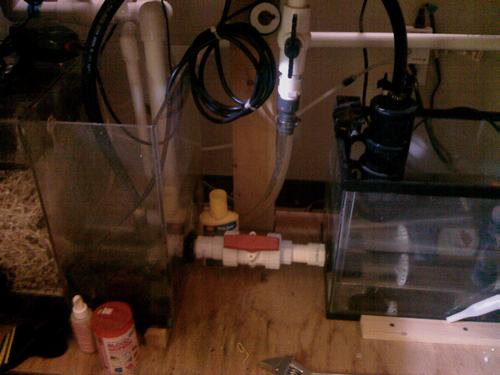
Wow. This is absolutely exactly the same setup I'm doing on the 120g planted freshwater in my office. I snapped a picture, sorry if it's bad, it was with my phone. My return pump is also a 9.5.
In my case, the 10g tank is used to provide extra return capacity, and my sump is a CPR wet/dry filter.
I used a 1" valve and bulkheads. In my situation, the pump was easily able to overwhelm the connection and cause the system to cavitate. I solved it easily enough. I have a Co2 reactor on the tank driven by a dedicated Mag 2. I put the pump in the sump, and put the reactor in the 10g (you can see it in the pic). This provided enough additional flow from one side to the other to balance it out with no further issues. Keep in mind that this setup only works because the gravity feed between the two tanks is keeping it balanced. You can't put a pump between two tanks like this without such an arrangement.
Also keep in mind that the level in the two sides will be equal, so if you want the fuge level to be deeper than the sump, you'll need to elevate the sump.
One other note of caution... 10g tanks are really easy to break when you tighten the bulkhead. I broke one doing this job. Luckily they are only $10.
Stress on the bulkhead is another MAJOR factor, as 10g tanks have a very low tolerance for this. I solved that problem by doing the following:
1. The connection is made using spa-flex, not rigid pipe. This allows for some amount of wiggle room, but not much.
2. If you look in the picture, I have wood blocks screwed to the stand floor around the 10g. This prevents it from moving in case the tank gets bumped by an errant elbow...
 

bigbills

Member
Thanks for the tips. I'm just not sure I understand your statement about this system being gravity fed. Could you explain that to me? Did you put a pump between the tanks? Or is the intake on you calcium reactor "pulling" water through the PVC and bulkheads?
I wasn't thinking of putting a pump between them. My plan was to put the Mag 9.5 return in the 10g, and keep my skimmer in the wet/dry. I was thinking of using 1.5" PVC to connect the refugium to make sure that it could handle more than enough GPH.
I can't tell from your picture, but is the waterline above the bulkheads?
 

scsinet

Active Member
Forget the pump for the moment.
I have a 1" bulkhead drilled into the sump and into the 10g tank, with a valve between them. The water drains into the sump on the left from the tank, flows through the connection to a mag 9.5 in the 10g tank.
When you put water into one side, gravity works to "even out" the levels on the other side. Because the connection is horizontal and both sides are at approximately the same level, there isn't a significant force on the water working to "push" more water through the connection.
In my case, the main return pump was pushing far more water than the connection could handle, so the 10g tank would empty out while the sump overfilled with return water. It was just too much for the connection.
So what I did to solve this was I put the pump for my Co2 reactor on the sump side, and dumped it into the 10g side. That provides some supplemental transfer from one side to the other.
My point was that you cannot use a pump arrangement like this as the sole means of transferring from one tank to the other:
This arrangement will work, as long as the drilled connection between the two tanks is large enough to handle the flow:
TANK DRAIN > SUMP > DRILLED CONNECTION > 10G > RETURN PUMP > TANK
This arrangement will never work. The pump connecting between the two tanks can never exactly balance the return pump and you'll have constant issues:
TANK DRAIN > SUMP > PUMP > 10G > RETURN PUMP > Tank
This arrangement is what I did. This works because the drilled connection keeps everything evened out:
TANK DRAIN > SUMP > PUMP AND DRILLED CONNECTION > 10G > RETURN PUMP > TANK
Okay, another way to look at it...
Say I wanted 500gph of flow from the return pump. That means that 500gph of flow has to take place between the two tanks. Makes sense, right?
Now, say the drilled connection between the two tanks can only handle 400gph. What will happen is that shortage will cause the 10g tank to empty out and the sump to overfill, as the connection between the two has been overwhelmed. This is my situation. So what I did is added a small pump to add about 200gph of flow from the sump to the 10g. This means that now the drilled connection only has to handle 300gph of the 500gph of total flow, which would be within it's capabilities, so the system works.
Does that make any sort of sense? I'm having trouble explaining it...
 
Top