UAS LED Algae Scrubber build

marvelfan

Member
I'm currently working on setting up a new 120 gallon reef aquarium. I discovered a thread on the algae scrubber site about upflow algae scrubbers (UAS). It seems that they have been successful replacements or additions to skimmers. I know there is mixed feelings about not running skimmers at all, but putting that aside, I've decided that since I will have a under-rated 65 gallon skimmer running on my 120 that I would run an algae scrubber along with my skimmer and see what happens.
I've decided to do an LED lit UAS. I'm working on a sketchup drawing of the set up, which I will post shortly.
I've decided to so a 6x6 screen. That is 36 sq-inches. From what I read you need either 1 real watt of light per square inch or 1/2 a watt LED per square inch.
For energy saving purposes I've decided to go the LED route.
I've also decided to only do a one-sided scrubber for the mean time.
I ordered 3W Red 660nm and 3W Royal Blue 450-455nm LEDs for the build. The LED build is only going to cost $46!
I ordered:
6 - 3 Watt Red 660nm LEDs
2 - 3 Watt Royal Blue 450-455nm LED's
1 - Mean Well LPC-35-700 Driver
8 - 3W LED Heatsinks - 3.5cm x 3.5cm x 1cm
10 ft of 22 gauge hookup wire
Thermal adhesive
Next I will hit up Walmart or a craft store for the #7 plastic mesh.
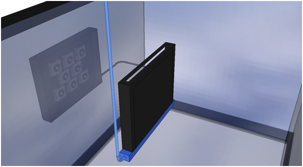
The plan is to encase the LED array and point it through the glass in my sump intake chamber at the screen, which will be be positioned over an airstone. I'm still working on how i'm going to build that portion, but it won't be too difficlut.
I'll post updates as I do the build and the results over the next couple months.
 

acrylic51

Active Member
I'm anxious to see pics.....Out of curiousity why the addition of the blue LEDs....Why not all red or add white into the mix instead of the blue......
 

snakeblitz33

Well-Known Member
Quote:
Originally Posted by acrylic51 http:///t/393850/uas-led-algae-scrubber-build#post_3505012
I'm anxious to see pics.....Out of curiousity why the addition of the blue LEDs....Why not all red or add white into the mix instead of the blue......

Algae needs blue light to thrive also. Red is only partial spectrum, whereas adding some blue by using chlorophyll A and B as well as carotenoids to grow the algae in a full spectrum of light to increase max growth potential.
Looking forward to the build!
 

2quills

Well-Known Member
Agree with what, Seth said. For me it was a toss up when it came to color choice for my scrubber led build. I know I definitely wanted 660nm red. But I opted for neutral white over blue. Reason was because the neutrals still have a respectable peak in the blue range but also covered a much broader range across the middle of the spectrum. My hopes are that the combo might perhaps be even more beneficial but I have yet to test it for myself. Although from what I have seen is that it show grow algae pretty well.
The O.P.s choice of the 660's and Royal Blue's is already a pretty proven combo from what I understand.
 

marvelfan

Member
Time to update. I've been studying Santa Monica's design using meal trays and 2 red led's. I'm going to attempt a similar design build. I think I may try to custom build an acrylic box instead of using meal trays. All scrubber builds I've read through are all pretty much the same. A screen configured to allow a combination of water/air to pass over the mesh and a sufficient light source to promote algae growth. It seems it all all comes down to your choice of materials and then adjusting the lighting schedule based on the nutrients in the tank. Below is my basic design.:

The left section will be mounted inside the sump. This will contain the screen and air source. I'm choosing to use a 6x8 inch screen. The minimum size recommended is a 3x4 according to the algae scrubber net forums. The 6x8 screen will provide a 48 square inch surface. 48 sq-inches equates out to a light source providing 48 real watts of light per side. I have decicded to only run it one sided. However, the use of LED's allows us to get away with 1/2 the wattage per side. In this build I will need to provide at least 24 watts of light for the 6x8 screen.
I'll be using 6 3-watt reds and 2 3-watt royal blues. Eight 3-Watt LED's equals 24 watts.
The right side (pictured above) shows the layout of the LED lights. The black cord is the power supply which will come in off of the 35W 700ma LED Driver.
The left side shows the screen, air stone and tube connected to an air pump.

The half with the air stone will have a slit in the top that will allow the bubbles to escape. I've seen this set up use either suction cups or magnets to connect the 2 halves between the glass. At the moment I think I'll end up using suction cups. From what I've read magnets involve encasing them in epoxy, and you have to make sure you find strong enough ones that work with your thickness of glass.
The final product should appear similar to this:
 

marvelfan

Member
MInor set back. My driver came today. Its a Mean Well LPC-35-700.
I wired my 8 3W LED's in series and then hooked up the driver. Tested the driver out put with a meter and every seemed ok. Plugged in the series of LED's and nothing. I then started to move the Negative end of the between the different LEDs to see if a solder joint was bad or maybe I just had a bad LED suddenly 3 of the LED's just flashed and burnt out. I hooked up the remaining ones and still nothing. Again I touched it between 2 of the LED"s and they burnt out (Minimum LED's needed are 3, so that was my fault that I killed those).
I'm sure I did something wrong or sloppy with my solder job. Luckily they were only about $1 or so each off eBay. So not a major loss, but still disappointing since I waited over a month for that driver to arrive. Decided to order the new LED's from Rapid LED and this time I went with solderless. Hopefully I'll get this algae scrubber going next week.
In the meantime I can work on the actual scrubber pad. I found some suction cups that I think will work out really well for mounting everything.
 

2quills

Well-Known Member
Quote:
Originally Posted by MarvelFan http:///t/393850/uas-led-algae-scrubber-build#post_3509583
MInor set back. My driver came today. Its a Mean Well LPC-35-700.
I wired my 8 3W LED's in series and then hooked up the driver. Tested the driver out put with a meter and every seemed ok. Plugged in the series of LED's and nothing. I then started to move the Negative end of the between the different LEDs to see if a solder joint was bad or maybe I just had a bad LED suddenly 3 of the LED's just flashed and burnt out. I hooked up the remaining ones and still nothing. Again I touched it between 2 of the LED"s and they burnt out (Minimum LED's needed are 3, so that was my fault that I killed those).
I'm sure I did something wrong or sloppy with my solder job. Luckily they were only about $1 or so each off eBay. So not a major loss, but still disappointing since I waited over a month for that driver to arrive. Decided to order the new LED's from Rapid LED and this time I went with solderless. Hopefully I'll get this algae scrubber going next week.
In the meantime I can work on the actual scrubber pad. I found some suction cups that I think will work out really well for mounting everything.
What method did you use to test the output of the driver and what were the results?
Did you run continuity checks on everything to check for shorts before you first powered everything up?
Were the 3 leds that flashed and fried out the 3 closest to the driver when you were doing your testing?
 

marvelfan

Member
Quote:
Originally Posted by 2Quills http:///t/393850/uas-led-algae-scrubber-build#post_3509603
What method did you use to test the output of the driver and what were the results?
Multi-meter (Shots of the out put are below)
Did you run continuity checks on everything to check for shorts before you first powered everything up?
No. I wired up all 8 LED's and then touched the positive and negative leads to the opposite ends of the LED series. What is a good method for testing? I should have used my meter to test continuity before powering it up!
Were the 3 leds that flashed and fried out the 3 closest to the driver when you were doing your testing?
Technically yes since I moved the leads. I'm guessing I should have completely wired in the driver (soldered) to the LEDs and not just manually touched the ends as a test?
I've diagrammed the way I had them wired in series. I double checked this 3 times before powering it. Hopefully this won't get confusing, but I did the math below and I'm wondering if I have the forward voltage to power the 8 LEDS? Hopefully someone can explain this to me. I think I have a good understanding, but needs some clarification. Thanks!

Here are some shots of the direct output of the driver. (I have 2 of these drivers and both output the exact same results)


I understand the DC output readings, as they match the specs sheet. Not sure how to read the AC readings though. I understand alternating current, but I don't see my 700 mA. In series the current should not divide over the LED's unlike the voltage. Each LED receives 700mA of current. According to the specs the low end DC Voltage is 9V and the high rage is 48 V. This should be self correcting based on its own feedback.
The Red LED's I used were rated at a forward voltage of 2.6V@700mA and the Blue were rated at 3.4V@700mA
9V/2.6V = 3.46 - meaning I should have used no less then 4 LEDs in my testing chain for reds.
9V/3.4V = 2.64 - meaning I could have used 3 Blues in series as a test safely.
This is where I think i went wrong. I tested 3 reds in series when they blew.
The rapid LED's I just ordered are rated as follows:
Red (Solderless Philips Rebel ES 660nm Deep Red) - 2.4V @ 700mA
Blue (Solderless Philips Rebel ES Royal Blue LED)- 3.0V @700mA
This is the way I plan to connect them R-R-R-B-B-R-R-R
(2.4 * 6)V + (3.0 * 2)V = 20.4V

There is a Max driving DC Voltage of 48 V.

48V/20.4V =2.35 V
per LED - Given this, Does this mean that there is not enough voltage to drive the forward voltages of the LEDS (2.4V and 3.0V)?
Rapid LED says you should be able to drive 3-14 LED's with the LPC-35-700.
 

acrylic51

Active Member
I'm confused in the math......Earlier in the post you talk about the forward voltage being 2.6v for the reds then down during your calculations where did you come up with 2.4v........
 

marvelfan

Member
Quote:
Originally Posted by acrylic51 http:///t/393850/uas-led-algae-scrubber-build#post_3509707
I'm confused in the math......Earlier in the post you talk about the forward voltage being 2.6v for the reds then down during your calculations where did you come up with 2.4v........

The first set of numbers and calculations were the chinese ordered LED's which I blew up. - i was trying to see why that happened. I should have done these calculations before hand. I'm learning this stuff through costly mistakes. Now I understand the minimum LED rule. Just trying to confirm that the driver will drive all 8 LED's (I don't see why it wouldn't, as I believe the forward current is what really matters. Since the current will be 700 mA for all LED's in series they should illuminate.
The second set of number are the new Rapid LED's I just ordered last night.
 

acrylic51

Active Member
Ok....cause I was sitting here at my desk and brewing the numbers and thought something was out of sort, because I remembered you saying something about different LEDs, and that would explain the difference in the fv.
I'm rusty at the calculations since my LED build is a bit off, but something doesn't seem right.....Hopefully Corey will bail me out and correct my ignorance, but I don't understand where the 9v even comes into play.....The max voltage of the driver is 48v. Determining the fv would be 2.4*6=14.4v for your reds..... fv for blues by my math would be 3.0*2=6v. So again bear with my ignorance, but adding your voltages of both colors would be 20.4v. Well under the specs of the driver.....Now why wouldn't you then take 48/20.4=425ma.......

Again my math sucks and memory sucks if I don't look at it everyday.....Hopefully Corey will chime in.....
 

marvelfan

Member
This is a quote from a site (can't link):
Quote:
In this example we will use the Meanwell LPC 35-700 and the Cree XT-E 5 watt LED. According to the PDF Data Sheet the LPC 35-700 has a forward voltage range between 9 and 48VDC. The Cree XT-E PDF Data Sheet shows a forward voltage range of 2.85 to 3.4. The forward voltage range of the LED is based on current and heat. Generally the higher the current and heat the more the forward voltage drop. For the Drivers the forward voltage range is based on the individual components. The published forward voltage range may be slightly off which is why we recommend to pad the book answer by 1 LED. Now for the book answer…For the LPC-35-700 with a minimum forward voltage range of 9 you would simply divide this by the minimum forward voltage of the LED. 9/2.85=3.15 or 4 LEDs because you must round up on the minimum side. For the maximum number of LEDs you would take the maximum forward voltage of the LED (3.4 VDC) and divide the maximum forward voltage rating of the driver (48 VDC). 48/3.4=14.11 or 14 LEDs maximum. In our experience and field analysis these numbers do work for the Mean well LPC 35-700
Does that make sense. The voltage range is self adjusting based on load. But will at minimum be 9V and maximum 48V based on the load. That's the way I understand it. So there are 2 calculations to be made. One for the minimum load you would need to not overload your component and one to find the maxium load the driver can handle before it can't power the components.
if the forward voltage is 3V for an LED.
9V (miniumum Driver voltage)/3V (Forward Voltage of one LED) = 3 LED Minimum.(But the rule is add 1 to that, so a 4 LED String would be safest). If you used 2 LED's you would be putting 9 volts through compoenents that could only handle 6V - frying them.
The other calculation is the maxium driver voltage over the forward voltage of a single LED - 48V/3V - 16 LEDs. The driver can handle 16 LED's before performance is diminished.
That's my understanding.
 

marvelfan

Member
Quote:
Originally Posted by acrylic51 http:///t/393850/uas-led-algae-scrubber-build#post_3509790
I'm rusty at the calculations since my LED build is a bit off, but something doesn't seem right.....Hopefully Corey will bail me out and correct my ignorance, but I don't understand where the 9v even comes into play.....The max voltage of the driver is 48v. Determining the fv would be 2.4*6=14.4v for your reds..... fv for blues by my math would be 3.0*2=6v. So again bear with my ignorance, but adding your voltages of both colors would be 20.4v. Well under the specs of the driver.....Now why wouldn't you then take 48/20.4=425ma.......

Again my math sucks and memory sucks if I don't look at it everyday.....Hopefully Corey will chime in.....
The other thing I noticed is that you are dividing two voltages 48V and 20.4V and coming out with a current (amps). 48/20.4 = 2.35 V (Voltage divides over components in series). So each component would receive 2.35V@700mA.In series all LED's will recieve the 700mA the driver is rated at.
I think that is correct?
Corey HELP!!!
TEACH ME PLEASE!
 

2quills

Well-Known Member
Ok, a couple of things that I see...
1st...Your choice of the 8 led count is a perfectly fine match for the driver. As long as the load is withing the minimun/maximum of 9-48 volts then you're good. This driver puts out a constant rate of current but the voltage with automatically adjust to the size of the load which in this case is approximately 20.4 volts. So no worries there.
2nd...You don't need to worry about the 120 volts A.C. If you've already tested the output voltage of the driver and it reads approximately 48 volts (not under load). That means the A.C. supply coming in from the power cord that's plugged into the wall is just fine. So I'm not sure where you placed the probes to try and check for 120v a.c. but unless you spliced into the power cord or opened up the driver then you weren't checking in the right spot.
3rd....You don't need to worry about the Alternat Current either if the driver output of 48 volts is fine. But if you ever needed to test for this in case your driver doesn't work you probably first want to check the outlet that it's plugged into. You'd also need to move the red probe of your meter in the bottom left hole of the meter that reads 10A fused and select the dial to test for Alternate Current in order to actually test the alternate current supply coming into the driver.
4th...D.C. (direct current) is what you want to check for to find out what the actual mA pushing through your leds are.. In order to do that you need to again move the red probe into the top left hole of your meter that reads 10 A fused and set the dial to test D.C. Current.
Testing for voltage and testing for current require two different methods. For voltages you simply test across the + and the - of which ever source you'd like to test, which could be a single led, multiple leds or just the driver itself.
Testing current requires you to run your meter in Series with the circuit. Meaning you hook it up in the string as if it were a led itself.
My guess is that you have a bad solder joint on one of the leds (possibly the 3rd in the string). Perhaps what is commonly referred to as a cold joint. When you placed your probe on the solder joint to test it you may have actually caused it to light up for a fraction of a second by helping it create a proper contact.
Can you physically see that the leds are fried? If not I would run a continuity check on all of them to make sure. It's simple. Leave your meter probes just as they are in the picture but select the dial to the weird looking symbol that's next to the Current selections. It's the symbol that looks like it has the universal symbol for sound next to it. Touch the probes together and you should hear a BEEP tone. Touch one probe to the positive side of an led and touch the other probe to the negative side. Do you hear a BEEP? If you do then that pretty much means the led is still good. If it doesn't BEEP then the led is pretty much bad.
Once you've confirmed either all of your old and or new leds are good (which you should always do before you solder) then do a continuity check on every single led to the heatsink after you solder. To do that you place one probe in either the - or the + pad of a led and touch the other probe to the heatsink. Do this on every single led but in this case if you hear a BEEP it's a bad thing. Mean's there is a short to the heatsink somewhere and it needs to be fixed before you power up the fixture.
HTH
 

acrylic51

Active Member
What I don't understand in your calculations how can you state the fv is (3).....when in all actuality the red is 2.4 and at 3v wouldn't you burn it up.....
 

2quills

Well-Known Member
Quote:
Originally Posted by acrylic51 http:///t/393850/uas-led-algae-scrubber-build#post_3509808
What I don't understand in your calculations how can you state the fv is (3).....when in all actuality the red is 2.4 and at 3v wouldn't you burn it up.....
I think that when he mentioned a 3v led he was speaking hypothetically. To illustrate that if a particular led required 3 volts at 700mA then you'd need at least 3 of them to meat the required minimum of 9 volts of load that the driver needs in order to even light the leds up.
Or at least, that's my guess. :p
 

marvelfan

Member
Quote:
Originally Posted by acrylic51 http:///t/393850/uas-led-algae-scrubber-build#post_3509808
What I don't understand in your calculations how can you state the fv is (3).....when in all actuality the red is 2.4 and at 3v wouldn't you burn it up.....
Yeah.. 3.0V@700mA is the rating of the blue LED's actually. 2.4V@700mA is the rating of the Red LED's. Thank you so much for the excellent explanation Corey. I visually see the burn marks on the diode, so I think they are shot, but I will perform the continuity tests.
Also, I think there was a short in my LED series, There was a spark that flew off between the LED and Heatsink at one point.
I'll do some test later tonight.
 
Top