Plumbing Re-design Blog

V

vince-1961

Guest
Okay, back to plumbing. The closed loop created above is working just fine, but it does not produce the alternating wave action for which I had hoped and it does not move as much water as I had hoped. My new pumnp has finally arrived. Iwaki 70 RLT. So, I'm going to use it to power the return from sump to tank.
I am concerned that it will send water through the UV light and the chiller too fast, thereby reducing the effectiveness of both units. So, here's a possible solution that has the added benefit of, hopefully, creating some more alternating wave action.
Attachment 219694
all comments are appreciated.
 

natclanwy

Active Member
I don't know what plumbing it like that will do to the flow rate of your pump but it isn't going to help it, all of the changes in direction are going to reduce the flow rate and also passing it through your chiller and UV light are going to reduce the flowrate. Water will follow the path of least resistance which may mean that path is not through your chiller or UV light because of the flow restrictions caused by both, which may cause other issues with both the chiller(freezing) and UV light(excess heat).
Have you thought about seperating the chiller and UV light from the closed loop and running them with a seperate small inexpensive pump like a Mag or Quietone?
One more suggestion is to check out Flow accelerators or Eductors, I have done a fair amount of research on them and they sound like they will have great benifits. I am going to be building an aquarium for our local Junior High and intalling a closed loop with eductors in that system. According to my calculations and confirmed by the manufacturer I should get close to 6000gph out of a Reef Dart pump including the flow induced by the eductors.
 
V

vince-1961

Guest
Nat,
I was counting on it to reduce the flow some, but I hadn't considered the possibility that it could be reduced too much!
The new pump (70 RLT) has amaximum head of 31 feet, so I figured it was plenty powerful to drive the diagramed system.
I was planning on using the old pump (an old, noisy Iwaki 40 RLT) to power my impact skimmer ... and only the impact skimmer.
 
V

vince-1961

Guest
I got a lot going one in my life, but I finally found a weekend to get back to the aquarium. So, here is a shot of all the equipment laid out for testing to see if it works. We're talking chiller and green Iwaki 70 RLT pump to replace the old, black 40 RLX-T that came with the aquarium when I bought it ....
Attachment 221362
Attachment 221363
Attachment 221364
and here is the blue print...
Attachment 221365
but first I ought to show the sump redesign ... see next post


V

vince-1961

Guest
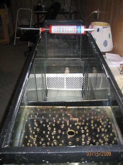
This design is to provide two mechanical filters, specifically a filter pad when the water first enters the sump and a skimmer. Otherwise the only "cleaning" this design will do to the water is to run it through rocks, the first of which is a $50 square man-made block of porous material I bought from some internet supplier. It will be directly under the drip plate, above the water line, resting on the first vertical piece of acryllic from the right. Actually, both of these sections will be filled with small chunks of D.I.Y rock, so the square block will not actually be on the acryllic, but on piled up rocks.
Notice that the first piece of acryllic on the right created a dead space where there is no outlet for the water that pours in from the top. This is my "pod farm", which most of you would call a "refugium" since it is a safe harbor (refuge) in which the pods can relax without fear of being eaten. Notice also that the 2nd from the right piece of vertical acryllic is painted black. That is to sheld the pods from the light which will be shining on the middle for the cheato and the far left for the phytopklankton. Notice on the far left a horizontal shelf, slightly inclined toward the left wall. This is where I will sit my plastic 2 liter Coke bottles for phytoplankton production. When (not if) they fall over, they'll fall toward the wall and not the water in the middle. So, theoretically, they should not fall over. (yea right!)
Take further note that there will be no sand in this sump, b/c the DT has a four inch deep sand bed for nitrate reduction. B/C no sand, and no protein skimmer in the sump or other source of air bubbles, the usual over/under/over baffles are absent.
Attachment 221366
Attachment 221371
Attachment 221368
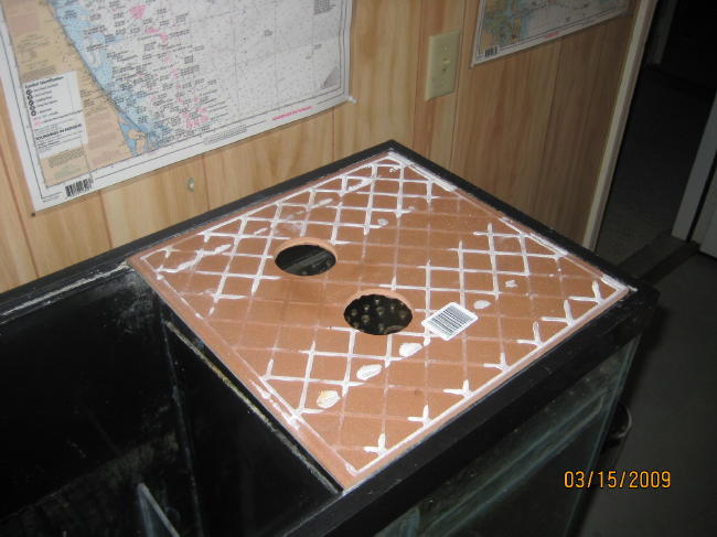
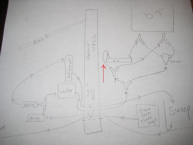
here are the holes for the drains. They'll dump directly onto a filter pad, which is changed daily.
Attachment 221369
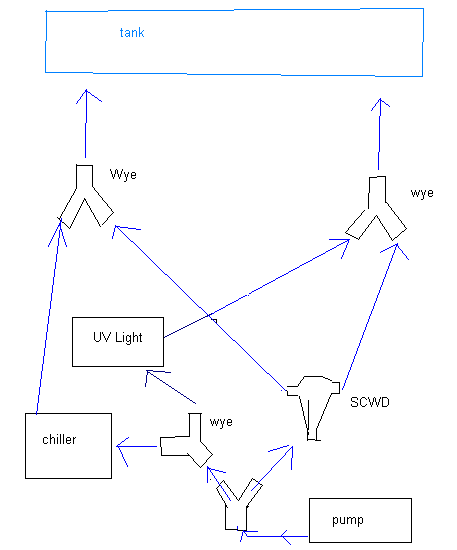
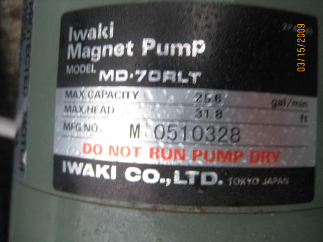
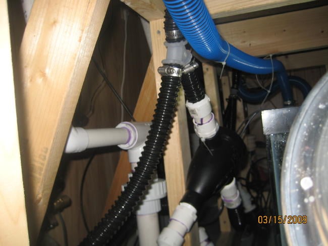
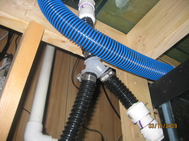
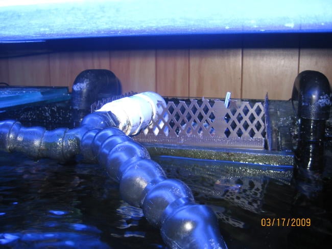
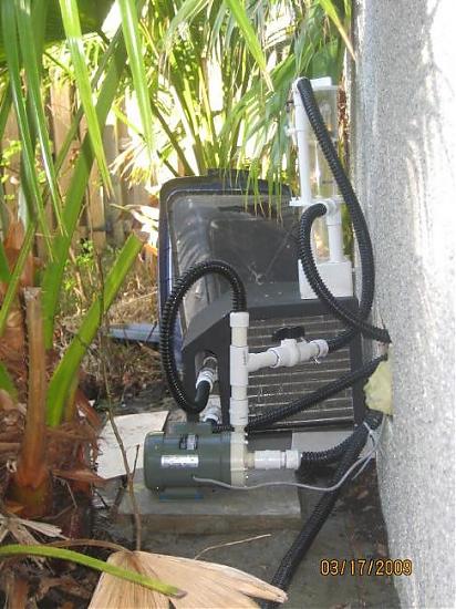
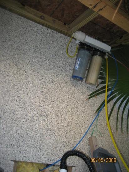
Notice that I increased the ID of the drains from 1" to 1.5" to account for the more powerful pump. I wish I could have eliminated the uphill section for the right drain, but if I had shortened the blue hose, there would not have been enough length to be able to slide the tile forward for access to the filter pad sitting on the drip plate.
Attachment 221370


V

vince-1961

Guest
The general idea of this plumbing was reduce the flow through the UV so that I did not have to spend money to double the length of the UV light, thereby increasing the time water is exposed to UV. I figured the new pump would send water through the UV so quickly as to render it ineffective. So, this design theoretically reduces the water flowing through the UV by 75%, meaning that only 25% of the water being pumped back up tp the DT runs through the UV, while 100% of it runs through the chiller and 50% of it runs through a SCWD.
The really nifty aspect of this design is the SCWD. Recall that I put two SCWDs on my closed loop. That didn't create the alternating wave action for which I had hoped, even though it is great for creating currents that are not constantly going in only one direction.
What I've done is routed a constant flow of water through both return pipes, but then, with the use of two WYEs turned "upside down", I have taken a theoretical 50% of the current and alternated it between the right and left returns. Hopefully, the end result will be strong surges every 30 seconds or so coming out of the right, then the left, return pipes. Given that water seaks the path of least resistence, we'll see how much fact resembles theory.
We begin the photos halfway through the assembly of the parts....
Attachment 221374
This shot shows the SCWD in first installation
Attachment 221376
close up of the upside wye.
Attachment 221377
God help me if it leaks...tubes everywhere!
Attachment 221378
what a jumbled mass ... or mess....
Attachment 221379
oh ... there's more.....


V

vince-1961

Guest
Recall that the whole idea here is reduce the noise. I am sensitive to constant humming noises. Can't hear the TV over the fridge and all that. Recall that there was an EXERIOR wall in the blue print.
here it is.... without a roof built over it yet .....
Attachment 221380
Attachment 221381
Attachment 221382
I'm calling it a day. It's late, I'm tired and I forgot the take photos of the rest of it.
Goodnight folks. (12:30 AM on a Sunday night.)


V

vince-1961

Guest
It's been 48 hours since last silicon job, which was adding spill-over guards for the built-in drain boxes in my All-Glass aquarium per photos. I have lost more than a few fish down the drain pipes for lack of drain guards. It may be ugly, be it's functional.
Attachment 221536
Attachment 221537
Re-filled sump, including the rocks (grr), plugged in pump. Looked over and noticed that one of the hoses had two pinhole leaks in the middle of the stretch. Same hose also leaked at Wye connection.
It's late and I'm too tired to mess with it tonight.
"Tomorrow is another day."
Red arrow shows which hose
Attachment 221535
Meanwhile, I started building the roof over the exterior stuff today. No pic of that, but here's the exterior stuff with hoses attached.
Attachment 221538
Attachment 221540


I have a question! How big or horsepower is your motor? That looks the size of some of the pumps on my swimming pools I clean! I do imagine that to much power would create bubbles just from the pushing effect thoughout the motor! The blades inside the motor will create a breaking effect in the water when spinning! And with it pushing lots of power! Well... u get it!
Also. Just from being in the swimming pool business!
When your were talking about,,, which inlet and outlets sizes uses more power! per the rating on the motor.. the pipes should be equal size inlet and outlet. .
When using smaller outlets and bigger inlets, your motor is working harder to push, using more power. When using smaller inlet and and larger outlet, your allowing your motor to spin more freely, also using more power. Your best best it to use the same inlet and outlet pipes, then maybe a spitter on the outlets.
 
J

jojo727

Guest
Hey Vince, just catching up with this thread. you're a mastermind dude, i'm scratching my head trying to grasp the concept of all this. lol
 
J

jojo727

Guest
hey, just placed my order for the 1" SCWD so look forward to me bugging you about plumbing. lol
 
V

vince-1961

Guest
I replaced that one little stretch of hose that was defective (had two pinholes in it) and turned it back on. Was losing water and it took me quite a while to figure out where. Was under the new pump. Turns out the rear casing (the part that holds the impeller) was cracked. See photo.
Attachment 221807
Attachment 221808
Attachment 221809
In the mean time, I attached my old pump and got it up and running. No matter where I put it or how I fiddled with the hoses, I couldn't get the impact skimmer to keep the water level steady, so I ended up putting it back in the sump.


V

vince-1961

Guest
That's what I get for buying it off of that vowel-Bay place where the winning bid gets the item. No big deal. I just googled replacement parts for Iwaki and clicked on the result that looked the most promising. The part cost $32. It ought to arrive soon enough.
Also ordered a grounding probe just in case there's stray voltage in the tank.
Yesterday I finished up the roof for the outside pump and chiller. Will post photos when I get around to it.
 
V

vince-1961

Guest
Sorry about the delay folks. It's been a while, so the plants have grown a bit.
Replaced the cracked part in the pump. Then had to have new pump serviced. It's running like a charm now. Good water flow everywhere. Nice and quiet too, except that I had to put the skimmer back in the sump. I couldn't get it to work right unless it was sitting in water.
Here are the pics I promised.
Attachment 229269
Attachment 229270
Notice the RO filter hanging underneath, totally out of the sun?
Attachment 229271
During these hot summer months, the chiller is doing a wonderful job.
SO QUIET! yipee.


V

vince-1961

Guest
Well, well well. I had forgotten that I was "blogging." Turns out that the complicated plumbing was just too complicated. Had a air leak in it somewhere that I never could find so I was blowing bubbles into the tank. Re-did it all. That was, apparently, three years ago. Wow. where has the time gone.
Now I'm looking to sell as I have basically just lost interest in it. I guess that's what happens when you you make the system practically self-maintaining.
Reckon I could post current photos.....
Vince-1961 is my name and email is a d o t c o m where the mail is HOT!
 
Top