Meowzer's LED build

acrylic51

Active Member
Yeah some good pics of the pot and some shot of the wiring going to and from the stars......I'm pretty sure it's something obvious, just were missing it. I did find a site, and I'm sure Corey has come across it as well, as how to test/check the pot to determine which leg is which. When everyone is wide awake it should be an easy check with the meter to determine what gets hooked where.....
Meowzer when he did have the LEDs fired and before trying to ramp them up with the Pot, where the LEDs bright? Dim?
 

meowzer

Moderator
Shawn...he says he thinks pretty bright....LOL....
Can you e-mail me that sight.....He just got up, and has to wake up some more, BUT if we had that to look at :)
I have a small digital camera that can do a video....charging up the batteries....we may try that to show the wires....BUT I know it takes a long time to load...LOL..so I'll do stills too
 

reefraff

Active Member
Quote:
Originally Posted by meowzer http:///t/387353/meowzers-led-build/320#post_3422002
Shawn...he says he thinks pretty bright....LOL....
Can you e-mail me that sight.....He just got up, and has to wake up some more, BUT if we had that to look at :)
I have a small digital camera that can do a video....charging up the batteries....we may try that to show the wires....BUT I know it takes a long time to load...LOL..so I'll do stills too
If he said pretty bright they probably weren't full power. @#$%^& MY EYES!!!! is the typical response when looking directly at the LED's

I think your problem is you've done something to annoy the reefing God of futility. Your only hope is to make a peace offering. He likes scotch. If you like you can send it to me and I'll pass it along to him.
 

2quills

Well-Known Member
Just waiting to see some pics.
So you're saying 4 of the whites are shorted and no good. And you're blues keep blowing all of the fuses when you turn up the potentiometer? Did we figure out how and why the whites blew? I am wanting to see how the pot and the walwart was hooked up together with the driver.
Now is probably not a good time to test vF's or voltage drops. I would asses the fixture for any and all possible damages that could have occurred in the wiring and go over all soldering connections with a fine tooth comb while you're waiting for your new fuses and leds to show up. Then there is a series of testing to do to check for shorts or any bad connections at any point on the fixture before it gets fired up for the first time.
Once that stuff is determined then you'll fire up one driver at a time with the pot turned all the way down low and will check vF's on the strings before we try to turn them up.
 

reefraff

Active Member
4 LED's dead in a string sounds more like a couple shorts than burnt out LED's. At least that would be a lot less expensive to resolve.
 

meowzer

Moderator
OK...the whites blew out cause of a short in the line
I pm'd you pics just a minute ago
WTH is vF?????????
 

reefraff

Active Member
Quote:
Originally Posted by meowzer http:///t/387353/meowzers-led-build/320#post_3422069
YES Reef, the shorts cause the LEDS to blow out
Did it actually kill the LEDs? When I was adding another circuit I forgot to solder on one wire. I had 9 LED's lite instead of 12. The wire was laying on the heatsink and I happened to get a little sloppy and had a solder booger touching the heatsink on one of the LED's. The current just ran from the solder booger into the heatsink and into the loose wire. It didn't kill anything. Its that luck vs good thing. I'd always rather be lucky than good. Luck comes naturally, good takes hard work and sweat
 

2quills

Well-Known Member
Quote:
Originally Posted by meowzer http:///t/387353/meowzers-led-build/320#post_3422067
OK...the whites blew out cause of a short in the line
I pm'd you pics just a minute ago
WTH is vF?????????
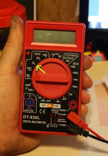
vF (forward voltage). You'll need to determine the forward voltages of each led on each string and write them down. This will allow you to determine the difference of the resistances on each string. Knowing the difference will help determine what needs to be moved in order to balance them. Ultimately the goal would be to have right around the same amount of voltage passing through each of the strings so that the intensity of the strings is equal to one another. For this we'll be using the meter set to the number 20 in the d.c. voltage settings on your meter.

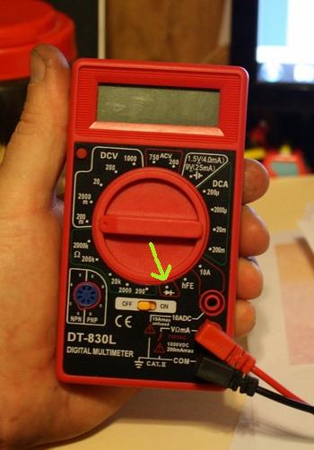
Diode testing and continuity checking. Diode testing is essentially what you did the the batteries by checking if the leds light up. But you can do the same thing with your meter on the diode test. With the power to the driver off you'll want to do is test each star by placing your probes on the adjacent stars. This will allow you to check not just the led itself but the soldering connections on the wires as well to make sure they're good. Try setting it to diode test and touch the red probe to a positive side of a led and the black probe to the negative side, the reverse the probes: red to negative and black to possitive and tell me what happens.
Diode mode:
 

meowzer

Moderator
Quote:
Originally Posted by reefraff http:///t/387353/meowzers-led-build/320#post_3422077
Did it actually kill the LEDs? When I was adding another circuit I forgot to solder on one wire. I had 9 LED's lite instead of 12. The wire was laying on the heatsink and I happened to get a little sloppy and had a solder booger touching the heatsink on one of the LED's. The current just ran from the solder booger into the heatsink and into the loose wire. It didn't kill anything. Its that luck vs good thing. I'd always rather be lucky than good. Luck comes naturally, good takes hard work and sweat
YES...it killed them....
 

meowzer

Moderator
Quote:
Originally Posted by 2Quills http:///t/387353/meowzers-led-build/320#post_3422088
vF (forward voltage). You'll need to determine the forward voltages of each led on each string and write them down. This will allow you to determine the difference of the resistances on each string. Knowing the difference will help determine what needs to be moved in order to balance them. Ultimately the goal would be to have right around the same amount of voltage passing through each of the strings so that the intensity of the strings is equal to one another. For this we'll be using the meter set to the number 20 in the d.c. voltage settings on your meter.

Diode testing and continuity checking. Diode testing is essentially what you did the the batteries by checking if the leds light up. But you can do the same thing with your meter on the diode test. With the power to the driver off you'll want to do is test each star by placing your probes on the adjacent stars. This will allow you to check not just the led itself but the soldering connections on the wires as well to make sure they're good. Try setting it to diode test and touch the red probe to a positive side of a led and the black probe to the negative side, the reverse the probes: red to negative and black to possitive and tell me what happens.
Diode mode:

OK....no clue what you are talking about in the first paragraph
IF they are different .......HOW different can they be from each other???? AND HOW do you even them up???
Second paragraph: when testing red to positive..etc...the led comes on
When testing red to neg...etc....nothing happens
 

2quills

Well-Known Member
Quote:
Originally Posted by meowzer http:///t/387353/meowzers-led-build/320#post_3422096
OK....no clue what you are talking about in the first paragraph
IF they are different .......HOW different can they be from each other???? AND HOW do you even them up???
Second paragraph: when testing red to positive..etc...the led comes on
When testing red to neg...etc....nothing happens
Forward voltages. Or the amount of voltage each led uses. You'll check each led to find the voltage that each one is using and write them down. The when you add them up for each string you'll be able to see which ones are using more voltage than others. Since the resistance across each one of the leds and soldering points will very slightly. At that point we'll be able to look at the individual voltages that you're wrote down and see which ones can be swapped around to help even out the strings. It sounds more complicated than it is. I know we talked about this before and it was covered in some of the info we sent. This is the balancing part of the fixture that we've discussed. The voltages don't have to be off by very much in order to create larger differences in current. And if these differences are great enough than they can be noticed visually.
Line 1: (3.02)(3.04)(3.04)(3.03)(3.01)(3.03)(3.03)(3.01)(3.00)(3.10)(3.15) = ? voltage
Line 2: (3.02)(2.95)(3.02)(3.10)(3.04)(3.27)(3.20)(3.02)(2.95)(3.18)(3.04) = ? voltage
Ok, so that test worked. I know you said Danny checked all the leds to make sure they light up and work. But he needs to check them the same way across the wires as well.
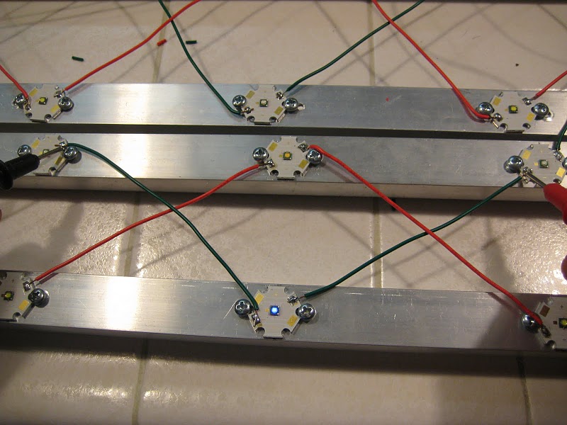
And then to check for shorts to the heatsink...check your negative and positive sides separately. He's probably good on the blue side already. But never hurts to check to be sure.

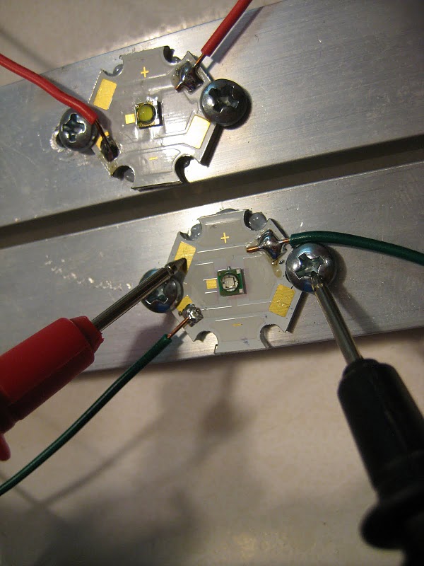
 

meowzer

Moderator
OK...will show him this tomorrow.....I know he has tested all different ways....for all I know he as done the above

there has been SOOOO much info flying back and forth...as I said...I AM LOST....I am basically the middle person here.....passing info from you guys to him...and I do not understand much of it
 

2quills

Well-Known Member
Quote:
Originally Posted by meowzer http:///t/387353/meowzers-led-build/320#post_3422120
OK...will show him this tomorrow.....I know he has tested all different ways....for all I know he as done the above

there has been SOOOO much info flying back and forth...as I said...I AM LOST....I am basically the middle person here.....passing info from you guys to him...and I do not understand much of it
It's cool. Just take it one step at a time. I know he's probably in a hurry to get it done before hunting season but your at the point now with the wiring that is the most crucial part of the build. You have a lot invested into it at this point, too much to not take the time to make sure it's right and it's safe since it's critical for the whole thing to function properly.
 

meowzer

Moderator
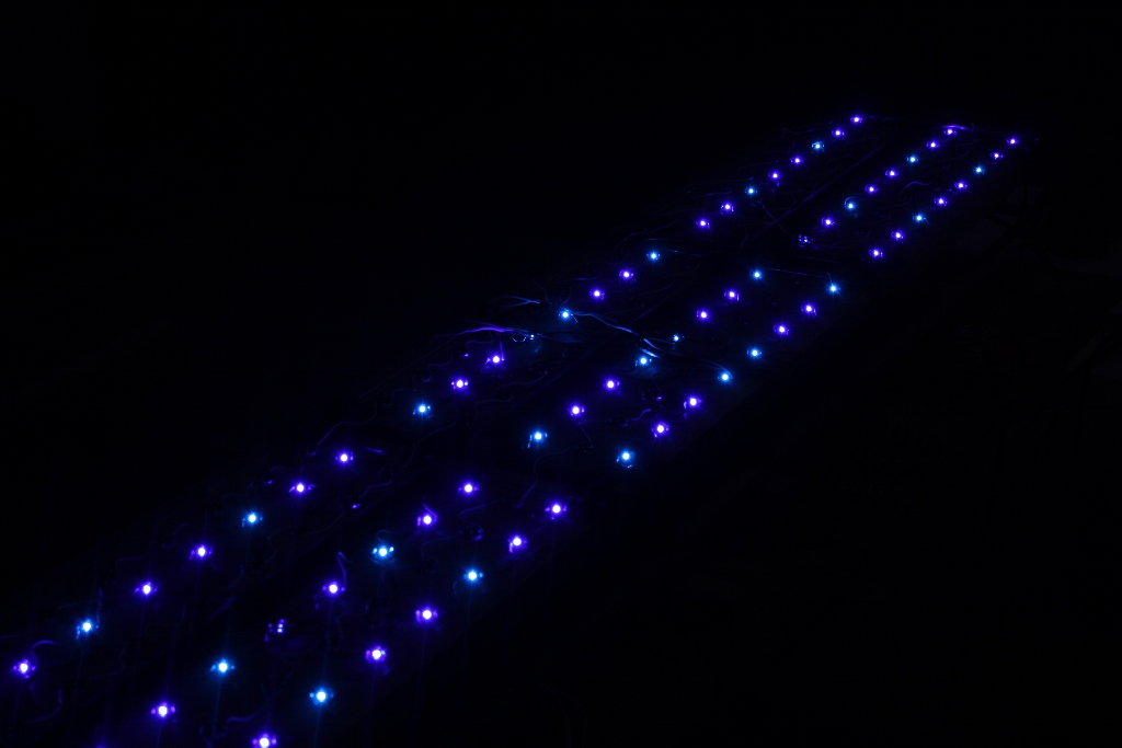
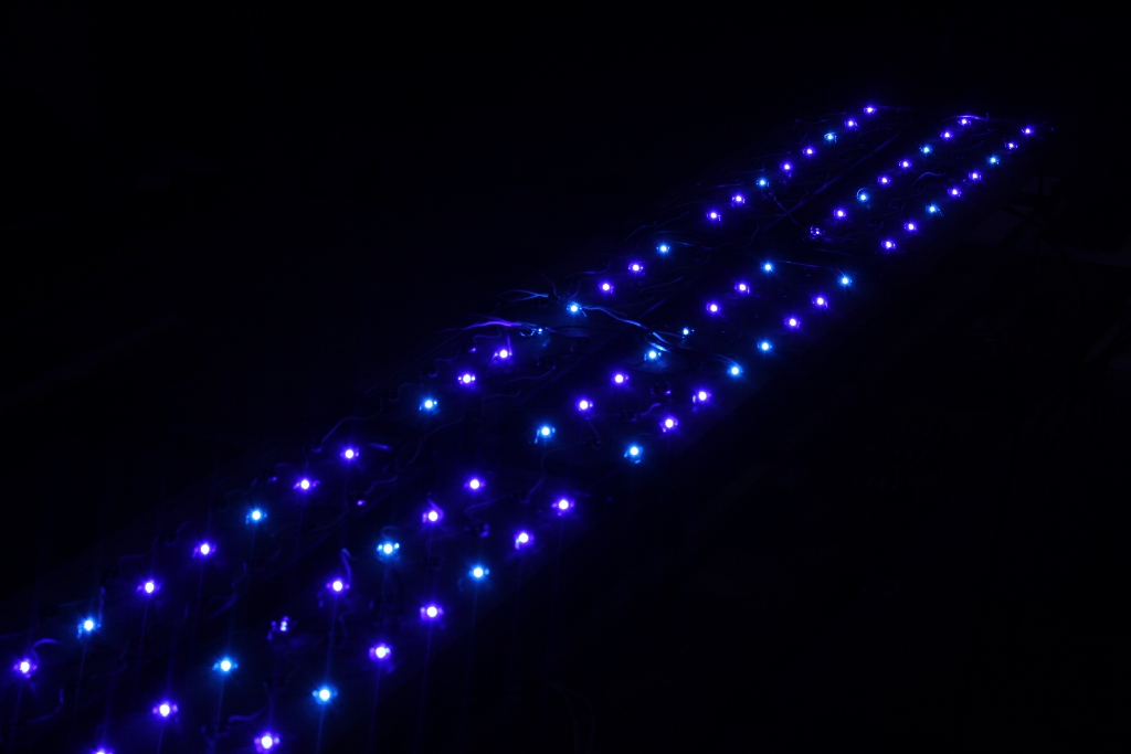
Blue LEDS on low...As soon as we started to turn the potentiometer (dimmer switch) up about halfway all the fuses blew :(
 

reefraff

Active Member
Are we there yet?
:)
Don't those drivers have internal adjustments for voltage and current? Could be they are set too high for your application.
 

2quills

Well-Known Member
Quote:
Originally Posted by reefraff http:///t/387353/meowzers-led-build/320#post_3423976
Are we there yet?:)
Don't those drivers have internal adjustments for voltage and current? Could be they are set too high for your application.
Danny is going to switch some wires around on the Potentiometer today. And needs to test the power coming from the 10v power supply so we know which one is actually the positive wire. So hopefully we should know something here today if it's going to work.
Reef: The dimmable version of these particular drivers don't have built in voltage or current adjustments on or in the driver itself. Everything has to be done with whatever dimming controls you're using and by calculating the right amount of leds and strings to use so that you end up with just the right amount of maximum current.
 
Top