aviator
Member
Yes. I've got the first circuit board cut, but am having a bit of an issue with the supplier of the optocouplers I'm using. Apparently they've decided to discontinue their production (stupid supplier) - so I'm having to go with a different model, which means the circuit board has to change . . . again . . . and get re-cut . . . again . . ah the joys of circuit design and production...
I've been told, privately, by several people that this is an "easy task" - that a timer like this is a simple build, the code needed to run it would run on an Arduino chip/platform, etc...
well, I'm here to tell those people that it's not as easy as you think it is to develop a timer like this that is commercial quality, can run non-stop 24/7/365, doesn't consume HUGE amounts of power, looks good, functions well, doesn't have bugs - and above ALL ELSE - it is SAFE FOR CONSUMERS TO USE... Sure, it could be developed on many different platforms, I'm sure the arduino platform can do this, and probably very well - but the skill of developing a device like this doesn't come in bit-banging the code to make a chip do what you want, thats just one small piece of the puzzle (albeit extremely important)
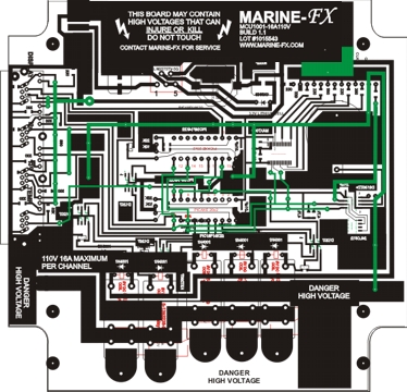
To this end I submit this image. This is the main board layout of the unit, notice it's not small, simple, or "easy" to reproduce. Why? because it's built properly, grounded properly, devloped properly, designed properly and it is safe. (oh, and if anyone is wondering, I've left out several very key traces, and two components and their traces, to prevent copying)

Sorry to rant, but it frustrates me to no end when people say "eh, I can do that... why would I buy yours for $XXX? you want to much money for a such a simple timer" - simple my arse! a fully developed circuit such as this isn't "simple" - sorry. This board contains both 5V DC and 110VAC - one of the biggest tricks is keeping one section shielded from the other - otherwise you will eventually destroy the microprocessor.
I also have all the connections moved over to RJ45 - and I've added two expansion ports (YEAH!!!) - this makes adding additional modules very easy in the future. Just plug them in, the system recognizes them. I still have to re-work the code a little to include the hardware expansion, but it shouldn't be that much work. The expansion ports are universal enough to handle adding more controlled outlets, adding LED driver modules, a probe module, etc...
But enough on the technical junk.
My hope is to have the beta units ready to ship before December 1. In fact, I might get to ship the first one before thanksgiving (hint hint)

I've been told, privately, by several people that this is an "easy task" - that a timer like this is a simple build, the code needed to run it would run on an Arduino chip/platform, etc...
well, I'm here to tell those people that it's not as easy as you think it is to develop a timer like this that is commercial quality, can run non-stop 24/7/365, doesn't consume HUGE amounts of power, looks good, functions well, doesn't have bugs - and above ALL ELSE - it is SAFE FOR CONSUMERS TO USE... Sure, it could be developed on many different platforms, I'm sure the arduino platform can do this, and probably very well - but the skill of developing a device like this doesn't come in bit-banging the code to make a chip do what you want, thats just one small piece of the puzzle (albeit extremely important)
To this end I submit this image. This is the main board layout of the unit, notice it's not small, simple, or "easy" to reproduce. Why? because it's built properly, grounded properly, devloped properly, designed properly and it is safe. (oh, and if anyone is wondering, I've left out several very key traces, and two components and their traces, to prevent copying)
Sorry to rant, but it frustrates me to no end when people say "eh, I can do that... why would I buy yours for $XXX? you want to much money for a such a simple timer" - simple my arse! a fully developed circuit such as this isn't "simple" - sorry. This board contains both 5V DC and 110VAC - one of the biggest tricks is keeping one section shielded from the other - otherwise you will eventually destroy the microprocessor.
I also have all the connections moved over to RJ45 - and I've added two expansion ports (YEAH!!!) - this makes adding additional modules very easy in the future. Just plug them in, the system recognizes them. I still have to re-work the code a little to include the hardware expansion, but it shouldn't be that much work. The expansion ports are universal enough to handle adding more controlled outlets, adding LED driver modules, a probe module, etc...
But enough on the technical junk.
My hope is to have the beta units ready to ship before December 1. In fact, I might get to ship the first one before thanksgiving (hint hint)


