415 Gallon Plywood Tank Build
- Thread starter acrylic51
- Start date
acrylic51
Active Member
Quote:
Originally Posted by SnakeBlitz33 http:///t/376802/415-gallon-plywood-tank-build/1200#post_3427378
Hey man,
Everything looks like it's coming together. I really like your return lines and your double closed loop design. I also like the idea of following the tides, many people don't do that, but I like it.
As far as that pic goes, I'de have to have a couple of pics and the dimensions of the fuge area that you have. From the looks of it, that eurobrace is really cramping it right there - but it might just be the angle that the pic was taken. Remember that scrubber screens can't be submerged... So, we'll have to figure out how to put at least four double lit screens over the top of that area.I would need the dimensions of the area that you are putting it in and the height between the surface of the water and the top of the stand ... clearance. We'll go from there.
I have a really, really good idea and design for multiple screens that I'll share with you, as long as the dimensions work. lol, I think it's funny how I've become the "local scrubber expert." hah
Dimensions?????
2quills
Well-Known Member
Quote:
Originally Posted by acrylic51 http:///t/376802/415-gallon-plywood-tank-build/1200#post_3427507
Corey do you have a shot of you sump drilled for the lines???? I have to go back and reread Bean's thread, but I thought he mentioned something about not using elbows going to the sump.....I thought something was mentioned about it effecting the full siphon?????
Not sure Shawn. I breezed through that thread quite a while ago but never really read the whole thing. I don't really see how an elbow would effect the siphon though.

acrylic51
Active Member
Thanks buddy!!!!! Your euro bracing looks wider than mine. What makes it a bit more difficult is my lines are 1.5 coming off the overflow as well. I want to actually bring my drain lines in from the side of the sump instead of coming over the top or through the euro bracing.
On page 154 of the overflow thread a guy used elbows...Actually quite a few, and Bean questioned why, and the possibility of it not flowing correctly....The poster was BrklynArch. His plumbing was way more elaborate than mine. I think with using SpaFlex down from the overflow box and put and elbow onto the end of the SpaFlex, and that way I can slide the elbow into the back of the bulkhead. Another option would be to come off both bulkheads with SpaFlex, but in the middle put a union so it could easily be disconnectd.....To many choices/options.
On page 154 of the overflow thread a guy used elbows...Actually quite a few, and Bean questioned why, and the possibility of it not flowing correctly....The poster was BrklynArch. His plumbing was way more elaborate than mine. I think with using SpaFlex down from the overflow box and put and elbow onto the end of the SpaFlex, and that way I can slide the elbow into the back of the bulkhead. Another option would be to come off both bulkheads with SpaFlex, but in the middle put a union so it could easily be disconnectd.....To many choices/options.
2quills
Well-Known Member
Yeah, I knew I would be drilling the brace before I built the sump so I went pretty wide with it and left extra material in the corners for that reason. If you did a sweeping curve with the spa flex and an elbow on the back on the back of the bulkhead I think it would work just fine without hurting the siphon at all. I think the more elaborate you make it (more elbows) the less efficient it becomes is all. Good thing about the 1.5" stuff is that you can use the long sweep elbows which is nice.
acrylic51
Active Member
Sorry Al!!!!! Haven't spent much time on the tank lately like I should be. As far as the overflow the original cutout was the long slots, but then I routed it open and made the removable covers. I'm pretty confident they will be fine though. Hopefully I'll settle down and get pumps ordered this week. Once I get the return pump I'm going to give everything a dry run and see what the overflow will handle.
al&burke
Active Member
Quote:
Originally Posted by acrylic51 http:///t/376802/415-gallon-plywood-tank-build/1220#post_3429219
Sorry Al!!!!! Haven't spent much time on the tank lately like I should be. As far as the overflow the original cutout was the long slots, but then I routed it open and made the removable covers. I'm pretty confident they will be fine though. Hopefully I'll settle down and get pumps ordered this week. Once I get the return pump I'm going to give everything a dry run and see what the overflow will handle.
I think I might just glue an eggcrate into the opening.
acrylic51
Active Member
That would work!!!!! I'd opt for a dab of silicone just so it could be removed easily if needed. I had thought about the egg crate, but wanted it flush with the panel. Also thought about how much support was left on the egg crate baffling and the pressure being forced against it constantly. That thought and the thought of it cracking, possibly sending little shards through my return pump deterred me.
On a side note if anyone's is interested in a pair of Tunze 6101's and a 7095 multi controller PM me!!!
On a side note if anyone's is interested in a pair of Tunze 6101's and a 7095 multi controller PM me!!!
acrylic51
Active Member
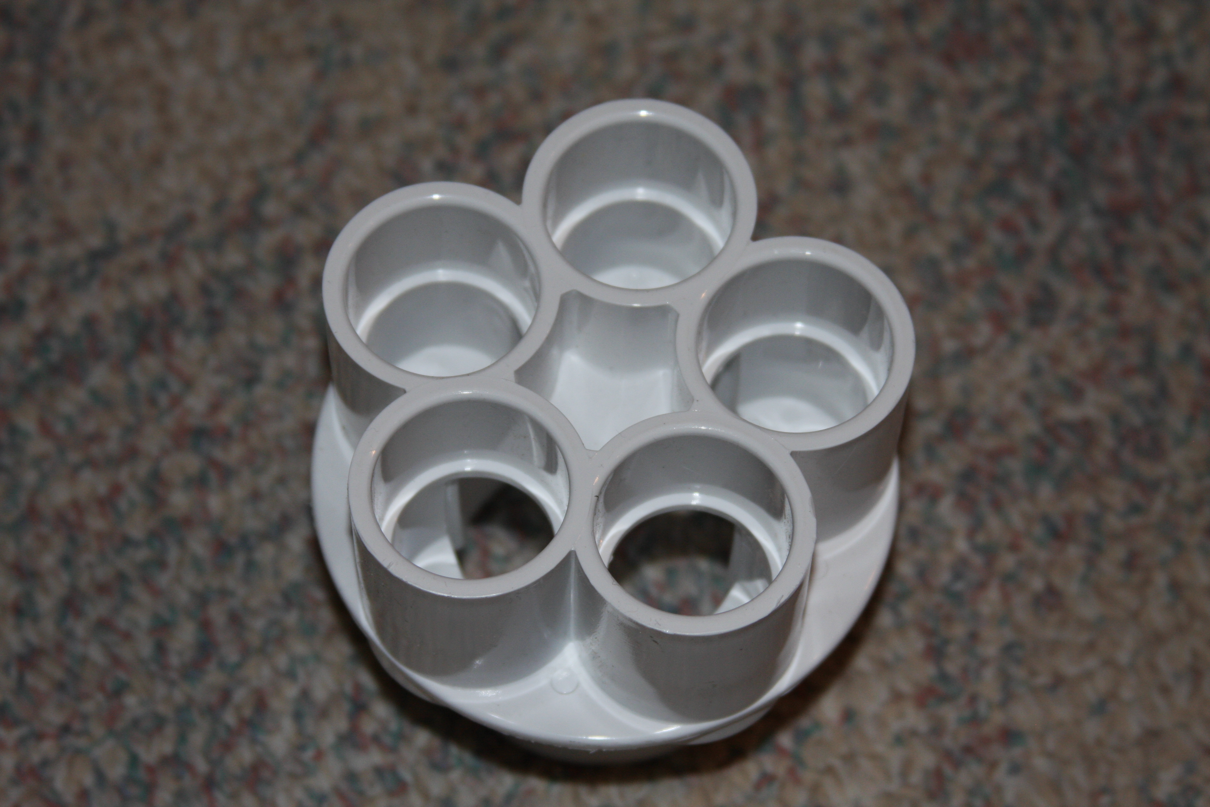
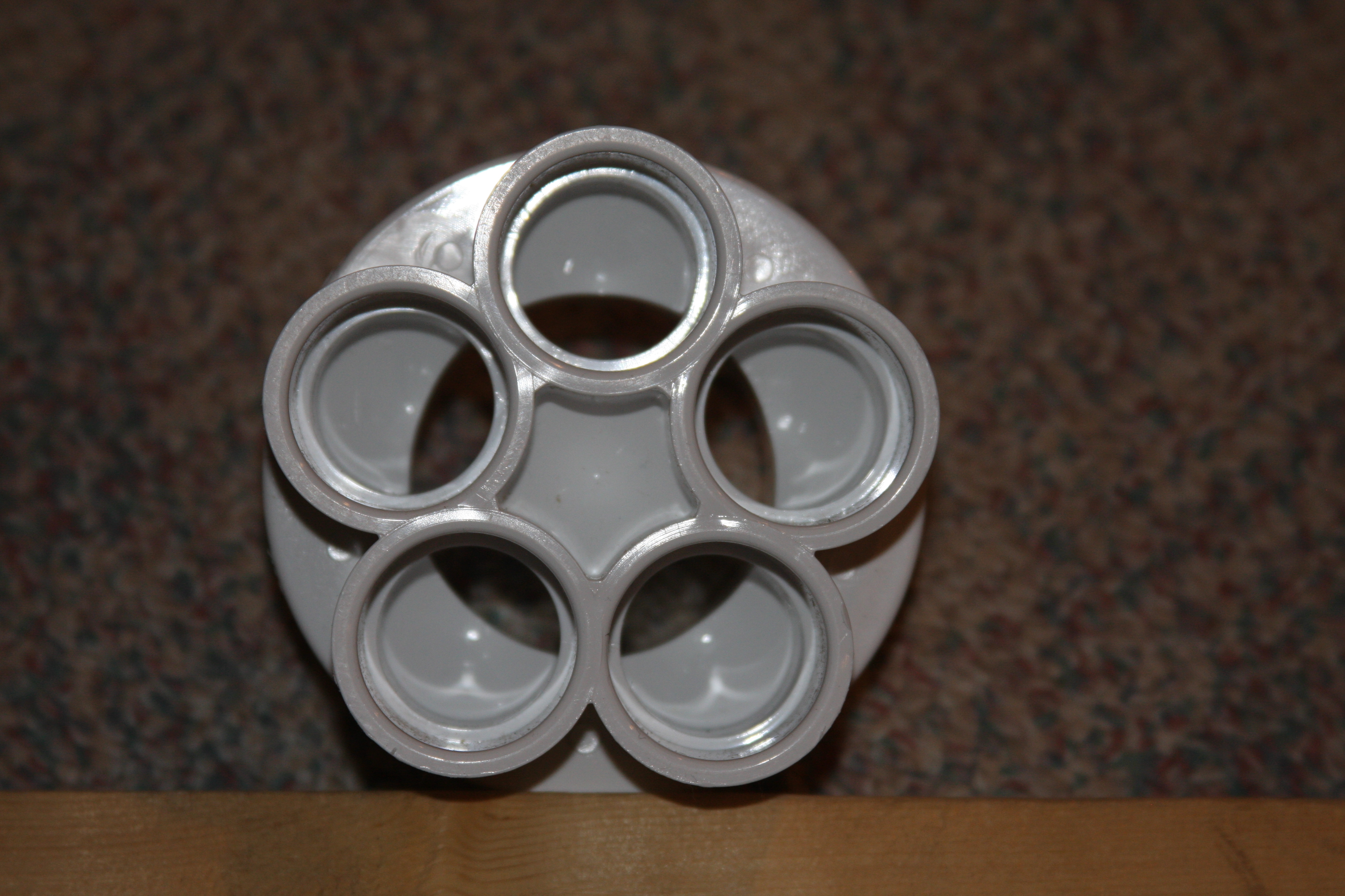
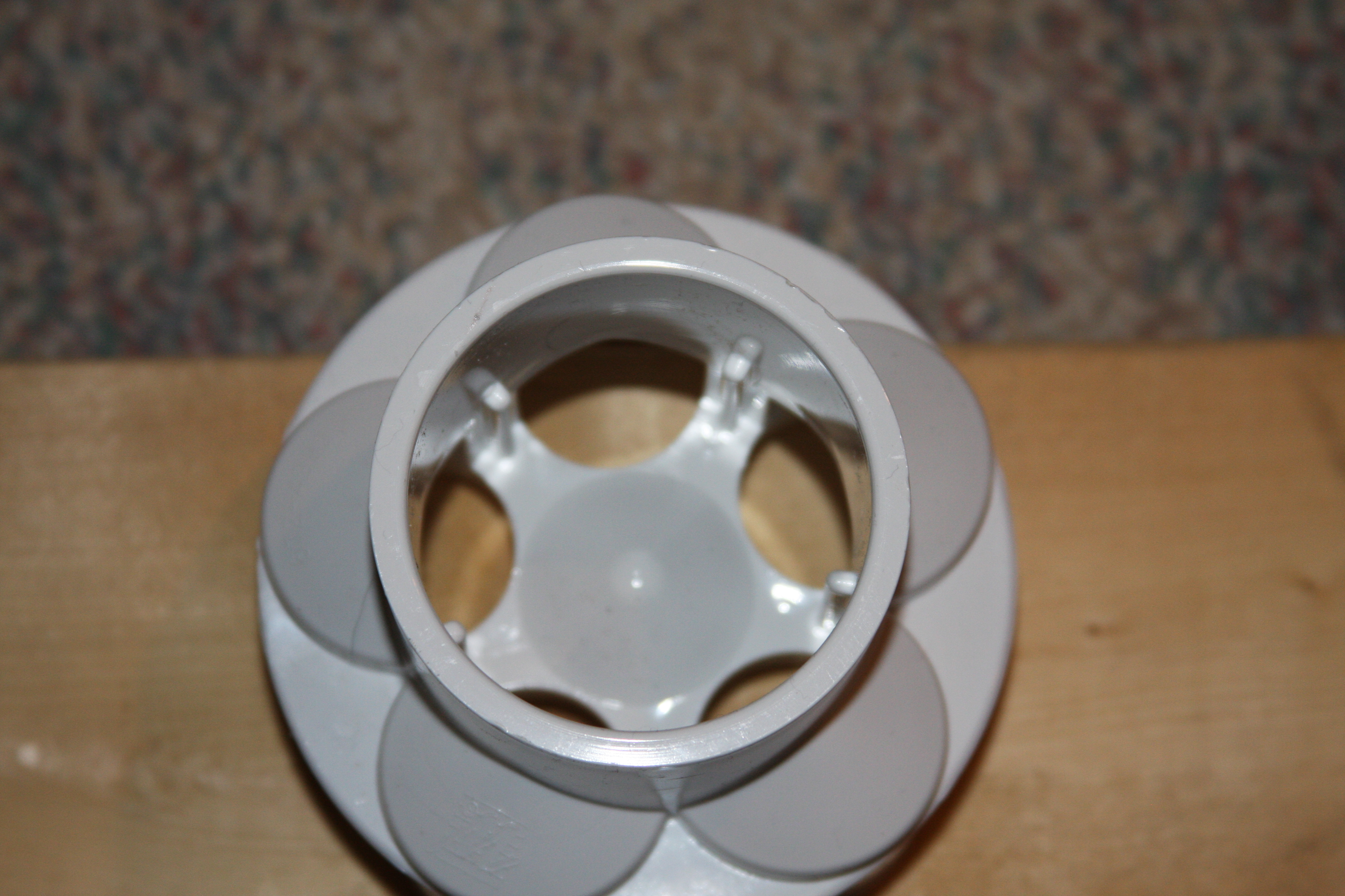
Corey sorry about the confusion in the text earlier today....Actually kind of hard to describe/explain what I was talking about......Here's a quick shot of the (2) that I'm looking at as far as the return pump manifold......
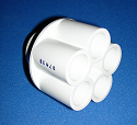
This manifold has a 2" input the bottom end and has (5) 1" ports.....Theoretically I only need 4 ports, but the 5th I'd use and reduce down to 3/8 fitting to feed the BRS reactors......
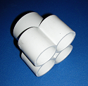
This is basically the same manifold system but the input is 1 1/2" and only has (4) 1" ports.....So with this option I'd need to tie into 1 of the return lines to feed the reactors.....
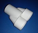
This is what they call a Wye manifold......When I was trying to describe this I was saying that I'd have to use a straight pipe off the pump output with a "T" and then glue a Wye on each end of the "T" to get me my (4) return lines.......This way I feel would be more work more plumbing....The input of the Wye is 2" and the (2) outputs are 1 1/2" which would have to be reduced down to 1" at the bulkheads anyways.
I think the first pic is a better setup for what I'm after.....I did finally talk to the guy at FlexPVC and they do have them in stock which was a major concern for me......Each return line regardless of which setup I go with will require a gate valve to regulate;balance the flow between the (4) return lines.
What's your thoughts.....

This manifold has a 2" input the bottom end and has (5) 1" ports.....Theoretically I only need 4 ports, but the 5th I'd use and reduce down to 3/8 fitting to feed the BRS reactors......

This is basically the same manifold system but the input is 1 1/2" and only has (4) 1" ports.....So with this option I'd need to tie into 1 of the return lines to feed the reactors.....

This is what they call a Wye manifold......When I was trying to describe this I was saying that I'd have to use a straight pipe off the pump output with a "T" and then glue a Wye on each end of the "T" to get me my (4) return lines.......This way I feel would be more work more plumbing....The input of the Wye is 2" and the (2) outputs are 1 1/2" which would have to be reduced down to 1" at the bulkheads anyways.
I think the first pic is a better setup for what I'm after.....I did finally talk to the guy at FlexPVC and they do have them in stock which was a major concern for me......Each return line regardless of which setup I go with will require a gate valve to regulate;balance the flow between the (4) return lines.
What's your thoughts.....
2quills
Well-Known Member
Cool. I've looked at those a little bit before. I wonder what the insides look like (how the flow is split). You're thinking the 5 port for 4 lines? Thinking you may have to stagger your valves or install them closer to the bulkheads perhaps. Doesn't look like there would be much room to have them side by side on another. Don't see why they couldn't work though.
acrylic51
Active Member
For the price it's worth a shot.....I think I'd get better flow than with a "T"???? Could be wrong, but worth a shot......Not sure exactly about the inside, but I'm figuring they are machine or ported to a degree somehow for flow.......
I thought the same thing myself....Actually I would have liked 2" input with 4-5 ports in 1 1/2" that way I could have possibly used "sweep elbows" off the ports, but haven't ever seen sweep elbows in 1"....Did order flex PVC to come off the manifold though, to eliminate crazy elbows. I had planned on putting the valves closer to the bulkheads due to space around the manifold, but I'm not sure if it would really matter if the valves were closer to the manifold or bulkheads?? In my mind I'm thinking possibly easier adjustment/balancing if they were closer to the manifold; whereas the water wouldn't have traveled as far down line only to be "choked" off a bit, where as it could be "choked off" closer to the pump are diverting it elsewhere closer to the manifold itself. Not sure if that made any real sense??????

I'll have to get some updates done here.....I do have to tell you those 2" tru unions are monsters.......
I thought the same thing myself....Actually I would have liked 2" input with 4-5 ports in 1 1/2" that way I could have possibly used "sweep elbows" off the ports, but haven't ever seen sweep elbows in 1"....Did order flex PVC to come off the manifold though, to eliminate crazy elbows. I had planned on putting the valves closer to the bulkheads due to space around the manifold, but I'm not sure if it would really matter if the valves were closer to the manifold or bulkheads?? In my mind I'm thinking possibly easier adjustment/balancing if they were closer to the manifold; whereas the water wouldn't have traveled as far down line only to be "choked" off a bit, where as it could be "choked off" closer to the pump are diverting it elsewhere closer to the manifold itself. Not sure if that made any real sense??????

I'll have to get some updates done here.....I do have to tell you those 2" tru unions are monsters.......
desertdawg
Member
Why not buy 3 wye's? One off the pump, then 1 wye off each side if the first one.
Also it doesnt matter where you put the valves, the flow will balance based on pressure not distance.
Also it doesnt matter where you put the valves, the flow will balance based on pressure not distance.
acrylic51
Active Member
Quote:
Originally Posted by Desertdawg http:///t/376802/415-gallon-plywood-tank-build/1220#post_3436803
Why not buy 3 wye's? One off the pump, then 1 wye off each side if the first one.
Also it doesnt matter where you put the valves, the flow will balance based on pressure not distance.
I did look at the Wyes a couple times, I think it more came down to bulk of all the fitting vs a more compact manifold.....You are correct on the valve placement.
desertdawg
Member
With the wye's you can split off the pump, run tubing to near the bulkheads and wye there. Two pipes running away from the pump should be less bulk than 4.
acrylic51
Active Member
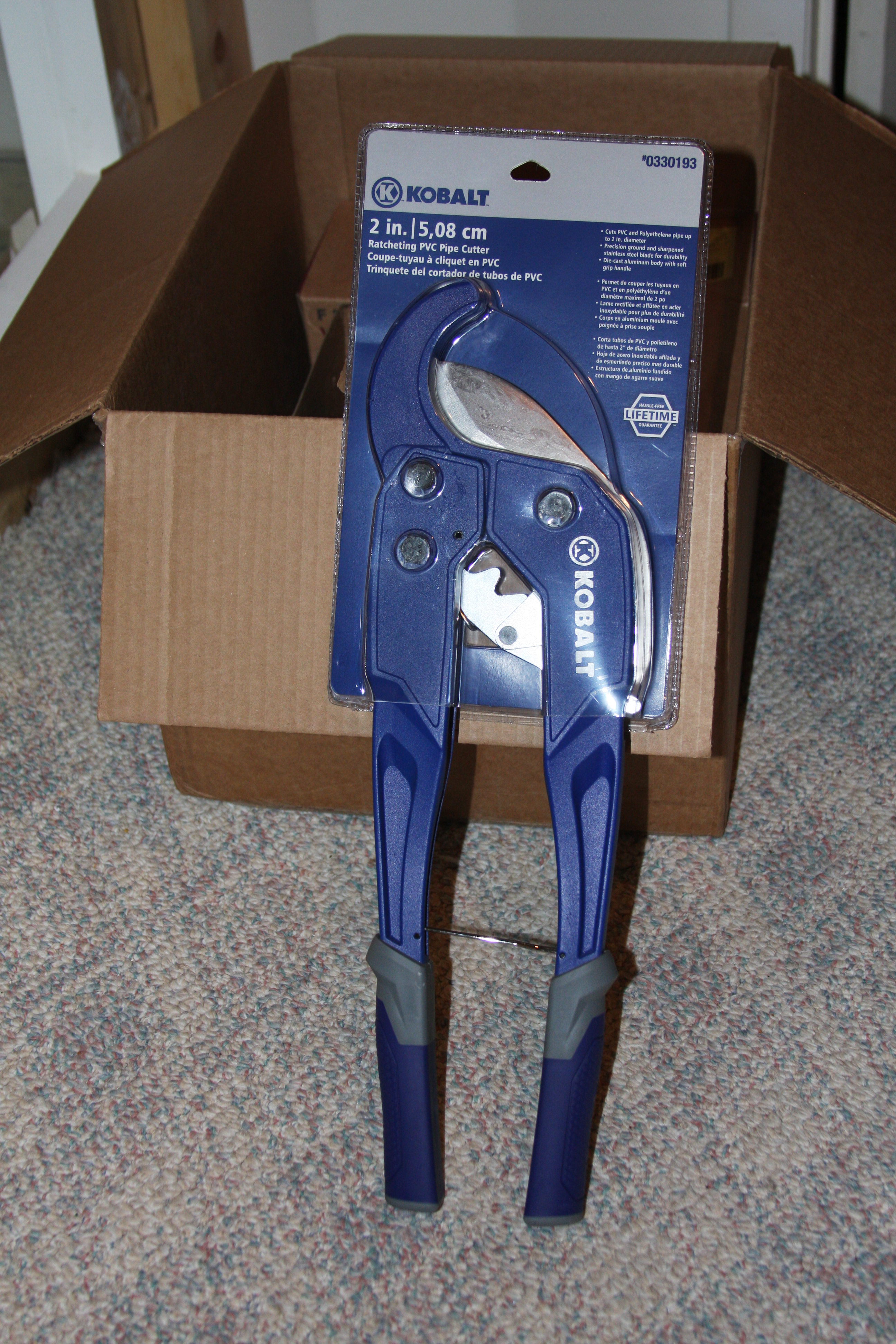
Sorry haven't updated lately....Super busy with work so limited time to work on the tank.....Have been ordering parts in, but along with work and back order of certain things needed, really slows progress. Since I'll be doing a lot of PVC cutting and really tiring walking from downstairs out to the garage to cut the PVC on the miter saw, I was browsing Lowes of course and came across these massive PVC cutters. They easily handle 2" PVC with no issues.........

acrylic51
Active Member
Quote:
Originally Posted by Desertdawg http:///t/376802/415-gallon-plywood-tank-build/1220#post_3437113
With the wye's you can split off the pump, run tubing to near the bulkheads and wye there. Two pipes running away from the pump should be less bulk than 4.
I am following you Desertdawg, but there would be running the 1 1/2" lines are bulky themselves IMHO.....That was my initial plan wias to bring (4) 1 1/2" lines off the pump area and then split them off when I get them in the general location where they need to be and then reduce that line down to 1" lines to feed the bulkheads. My thinking in all that is more head pressure with more fittings being utilized. It might all equal out in the end, but not sure.
I finally got the PVC manifold in, and have other parts on hand to make my own manifold, but leaning more towards using the pre built manifold just for the mere fact of a cleaner look underneath. I'm rather particular about "clean", and this setup would allow me a little more freedom to route lines more direct as well.......Corey I know you were curious about the manifolds....Here's couple shots........


acrylic51
Active Member
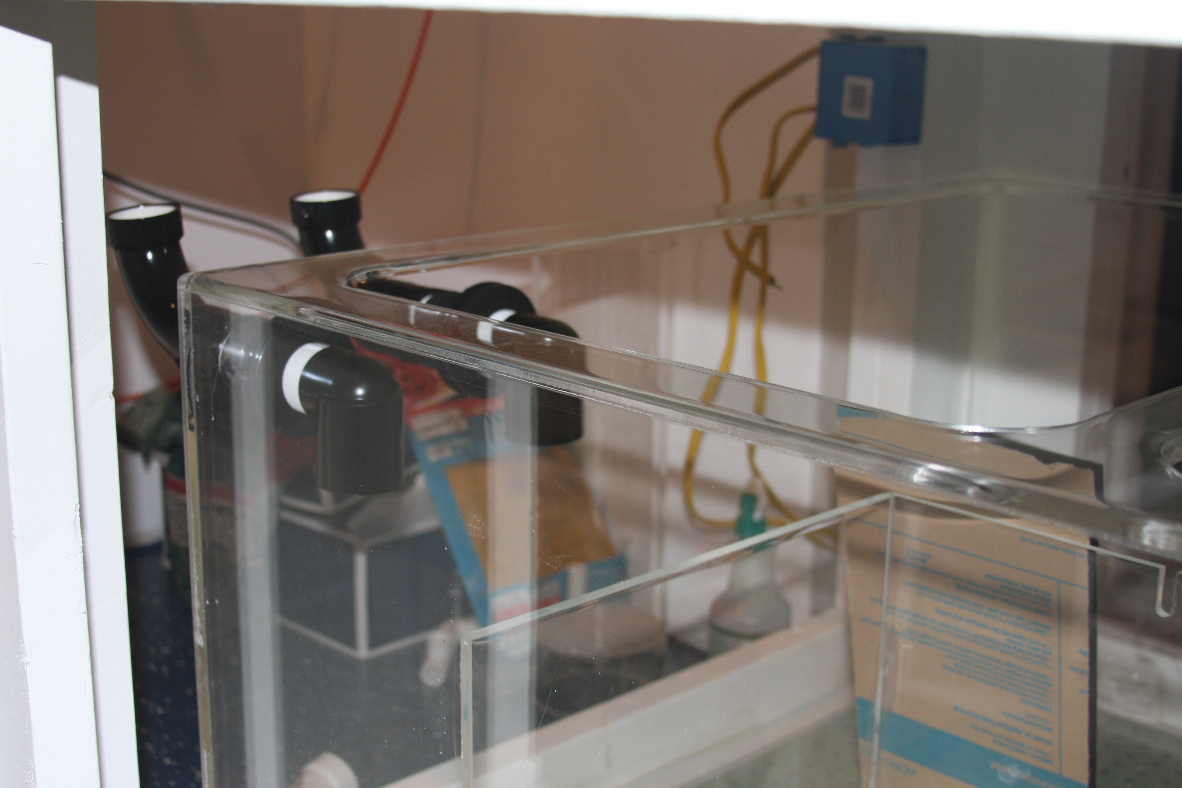
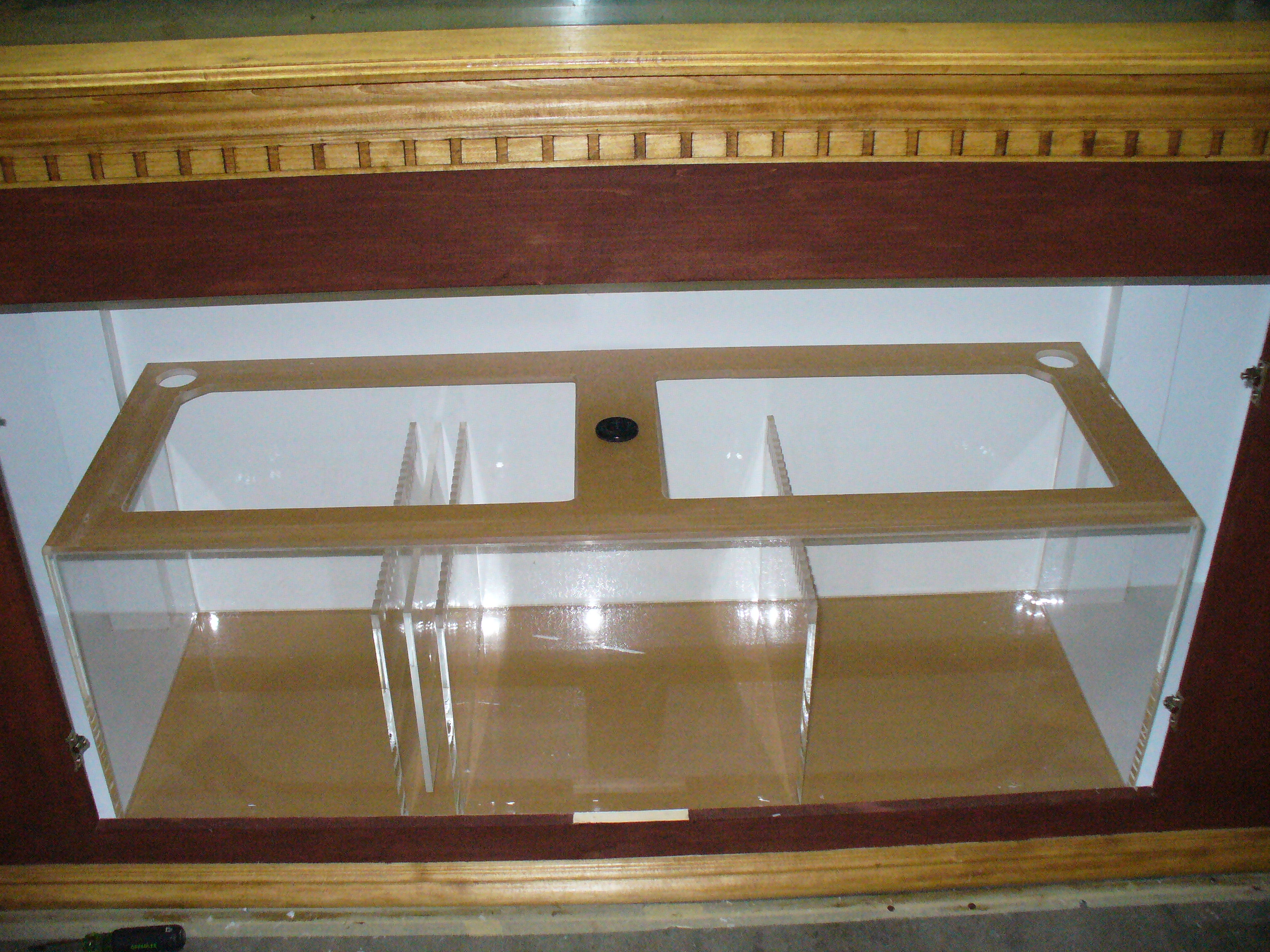
Started drilling the sump for the drains from the overflow......The 2 pictured are for the full siphon and the open channel pipe in the overflow box. I still have to drill the bulkhead for the emergency line which will be located over around the electrical box. I'm going to using the BeanAnimal Silent FailSafe overflow design. The down turned elbows inside the sump will have down tubes extending down into the sump. You can see acrylic sitting in the sump. The sump was built it seems years ago!!!!!!!

The add on is going to be a bubble tower. I don't foresee any issues, but I'd rather be prepared then to have to rip things apart again. Basically what I'm going to do is add an acrylic wall across where the overflow drains into the sump and route teeth into the bottom of the panel......The other change that is going to happen is I will be adding filter sock holders to the sump. These won't be utilized 24/7, but during initial setup, and for periodical water polishing they would be used. I had debated whether to purchase the holders or build my own, so ironically I decided to build my own. After I got them built I figured an easier method, but always the first is the worst........The sock holders will acomodate 4" ring filter socks.
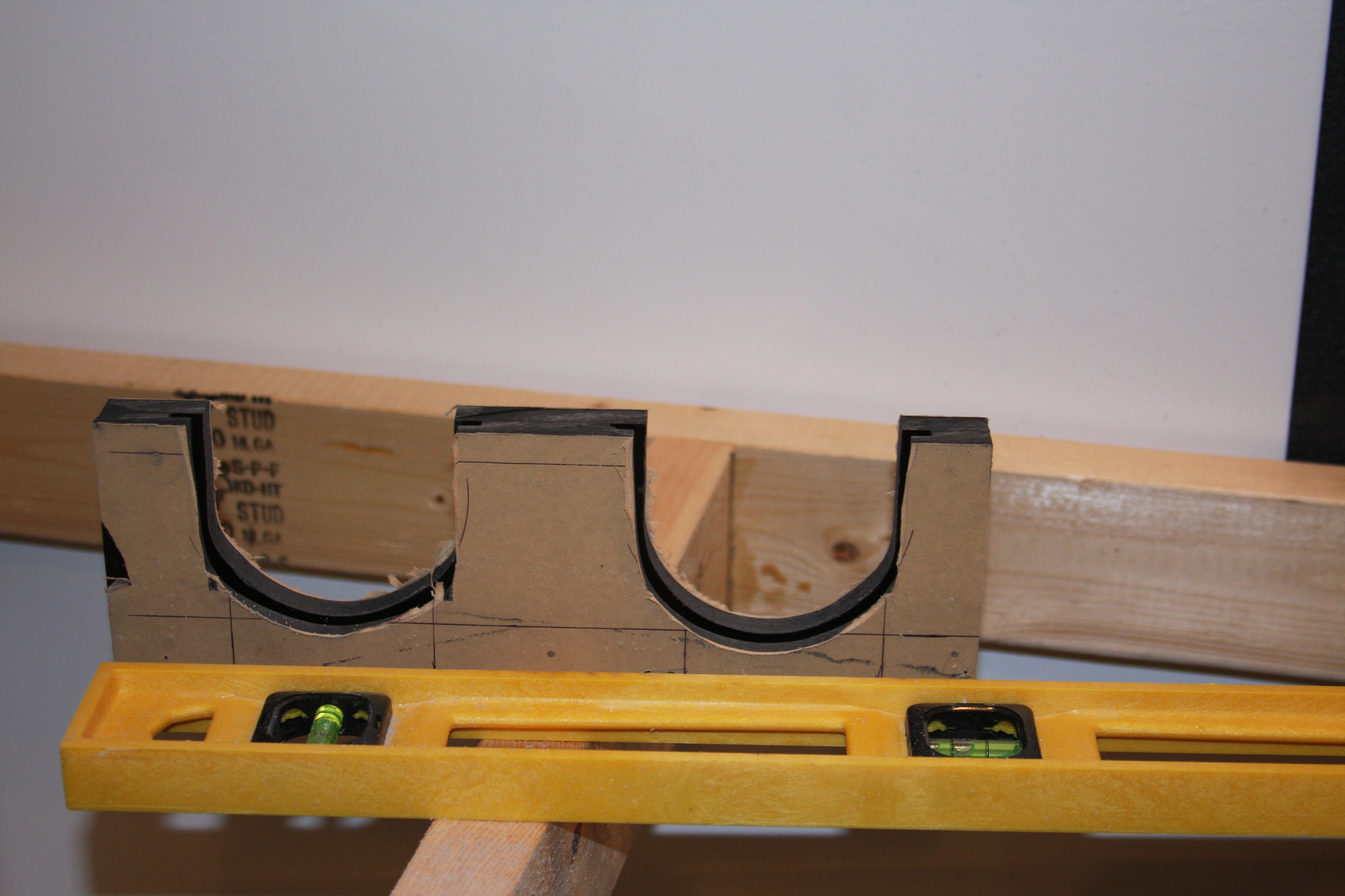
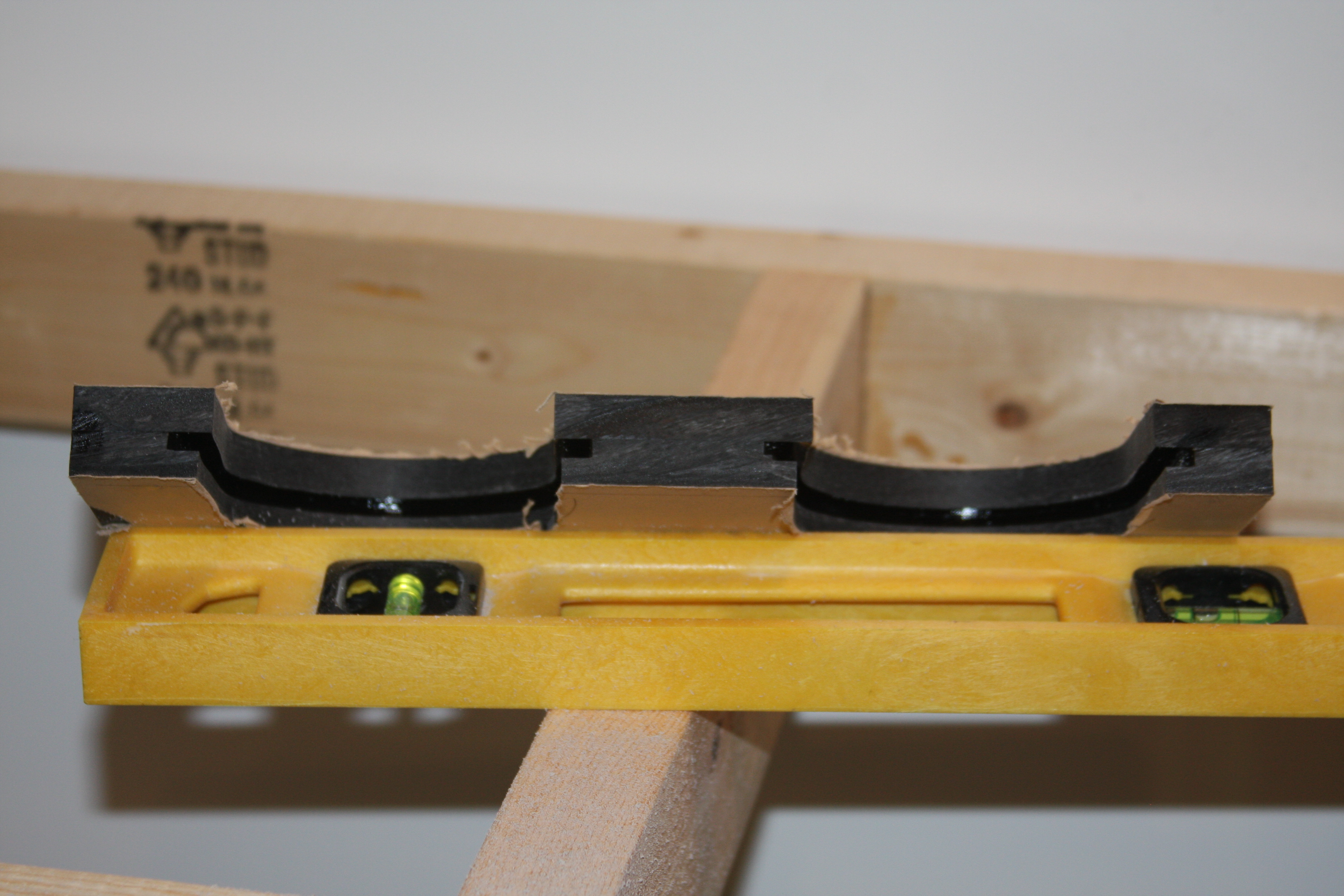
Dual sock holders.....The 4" diameter sock will slide into the cutout and groove easily and smooth!!!!!
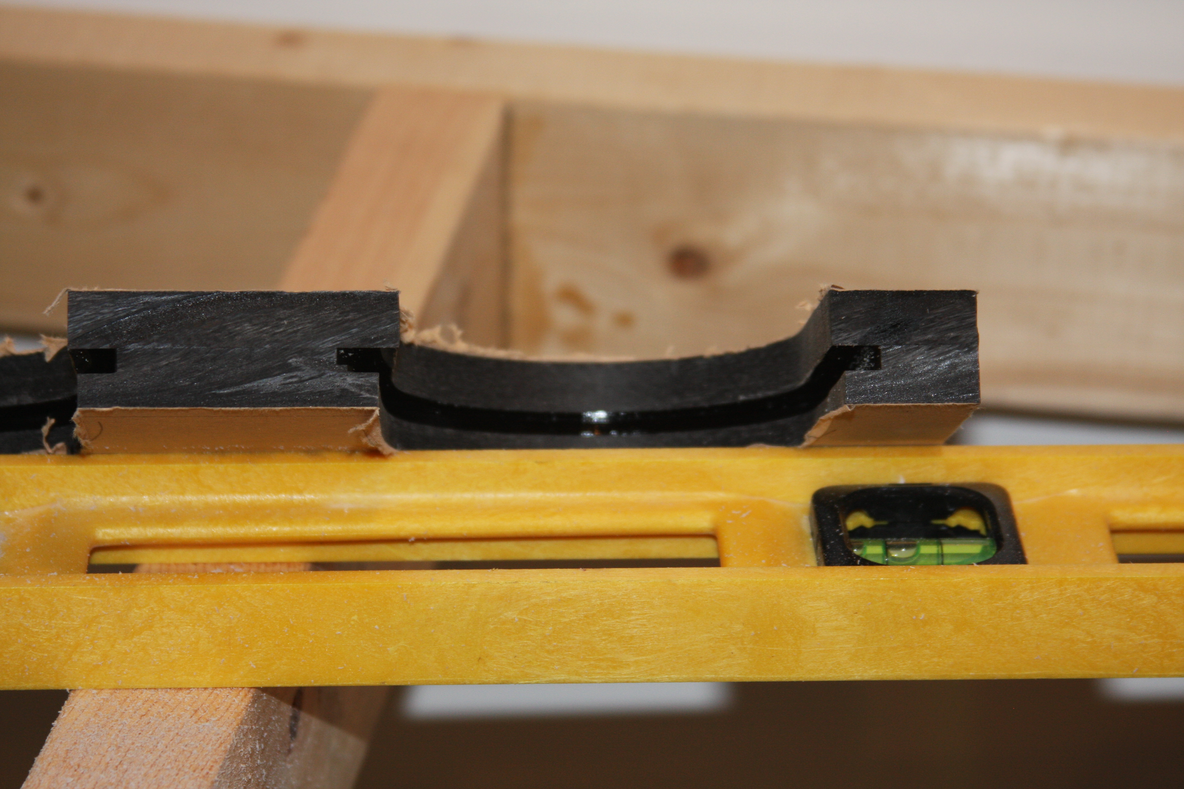
Close up of the groove cut for the filter sock to slide in and out.
