415 Gallon Plywood Tank Build

acrylic51

Active Member
Thanks Al.......I didn't even see that you had updated the drawings.......I spent quite a bit of time on the phone yesterday morning with Paul from OM.....I have to tell you, it's not many times you'd find a company owner who would get up at the crack of dawn and make a phone call/email to get you out of bed. Paul knows my schedule is hectic and we played phone tag all week, so Saturday morning worked for both of us.......
He gave me tons of ideas and stuff to think about......I'd honestly tell anyone, who's seriously thinking about water movement and how to make a tank move with efficiency to give him a call, and pick his brain. The nice thing about him is that he doesn't try to sway you to purchase his products. He already knew that I had the Tunzes and suggested if I could live with the cord issues it would save money......We all know I can't deal with the cords......And Vortech's don't have the adjustability needed for the job......
Anyways the drawings are perfect.......The only thing Paul and I did change or considered was either going with 6 bulkheads in the bottom or 8.....Not totally sure at this stage, but leaning towards the 8 bulkheads in the bottom, and ultimately there would be a total of 3 separate CL systems on the tank......I'm in the process of trying to gather info/thoughts on whether shutting down a CL for a period of time would actually cause any detriment to the system. The reasoning for wanting to shut a CL down for a period of time would be 1 to change the flow pattern up in the DT, but also to create a possible night time current flow during the lights out period......Again something that occurs in nature.
The bottom of the tank would actually consist of 8 bulkheads; which would be on 2 separate CL systems. The back wall would be on it's own CL as well......Early planning I would be opting to run the back wall CL alone during night time.....This by itself would slow the barrel roll down which will be running the length of the tank, but then the tank would have 2 distinct circular patterns during the night.....The flow would be rather slow/low across the bottom, but once the lights kick in, the flow would increase tremendously.
Everyones thinking????????
 

acrylic51

Active Member
Thought I'd post it over here Al instead of tying up the other thread, but I went to Lowes this morning and was looking for the extension you had shown. After I'm standing there in Lowes and seen them it made me remember to go home and look under the tablesaw/workbench area.....Guess what I had the whole time???? I had bought it when i was running new lines into the fish room, since I couldn't get the drill and the arbor bit into where I needed to go......Mines has the quick disconnect instead of a set screw to secure the bit handle in place.
 

acrylic51

Active Member
If you would see my garage you'd honestly understand, why I don't know or remember where or what I honestly have.....Actually it was buried/covered under saw dust from cutting all that MDF plywood I used to make jigs for the build.....I'm still trying to clean out all the acrylic shavings......The wife did say she would help me empty the garage and clean and put everything away......
 

2quills

Well-Known Member
I know the feeling. Every time I do a good cleaning I always end up finding stuff that I had forgotten I have.
 

al&burke

Active Member
My shop is a disaster as well I always laugh when I am looking for something and I find the thing that I was looking for when I was looking for something else. Never win too many projects not enough saltwater.
 

acrylic51

Active Member
Well at least I'm not alone.......Hopefully after all the work is done, I can finally reorganize everything in the garage. Anyways!!!!!
I've been slacking a bit with progress, but hopefully things will pickup quickly. Finally ordered and recieved the replacement canisters for the RO/DI unit. I thought I'd be slick and just be able to swap the canisters over onto the lids already mounted.....Well needless to say they didn't fit the old lids, so basically had to dismount everything and a majority of the plumbing to get everything swapped over, but that part is done....
Still need to order some bulkheads....Being a bit picky where I order my stuff from, and the ones I want/need or out of stock, but push come to shove I'll order from another source and pay a little extra......
Still haven't worked out all the details yet as far as the CL systems on the tank. The 1 CL system is already drilled. I was sure on the CL on the back wall of the tank, so that portion is already drilled and bulkheads installed. Also I installed the drains for the CL's and fabricated some bulkhead covers for them as well. I'm not a fan of the traditional bulkhead cover/strainers, so I usually make my own. Also started my plumbing working inside the overflow box. Still need to drill the 1 cap on the standpipe, but that won't take to long though.
Hopefully within the next day or 2 I'll get some updated pics up.....
 

acrylic51

Active Member
I might have to sneak downstairs and take a few pics....The tank is messy from drilling....The bulkhead holes I drilled in the euro bracing on the 1 end where I won't be able to use bulkheads I need to take the round sanding drum and widen the holes a bit, to allow me to drop the omni flex nozzles down through......
 

acrylic51

Active Member

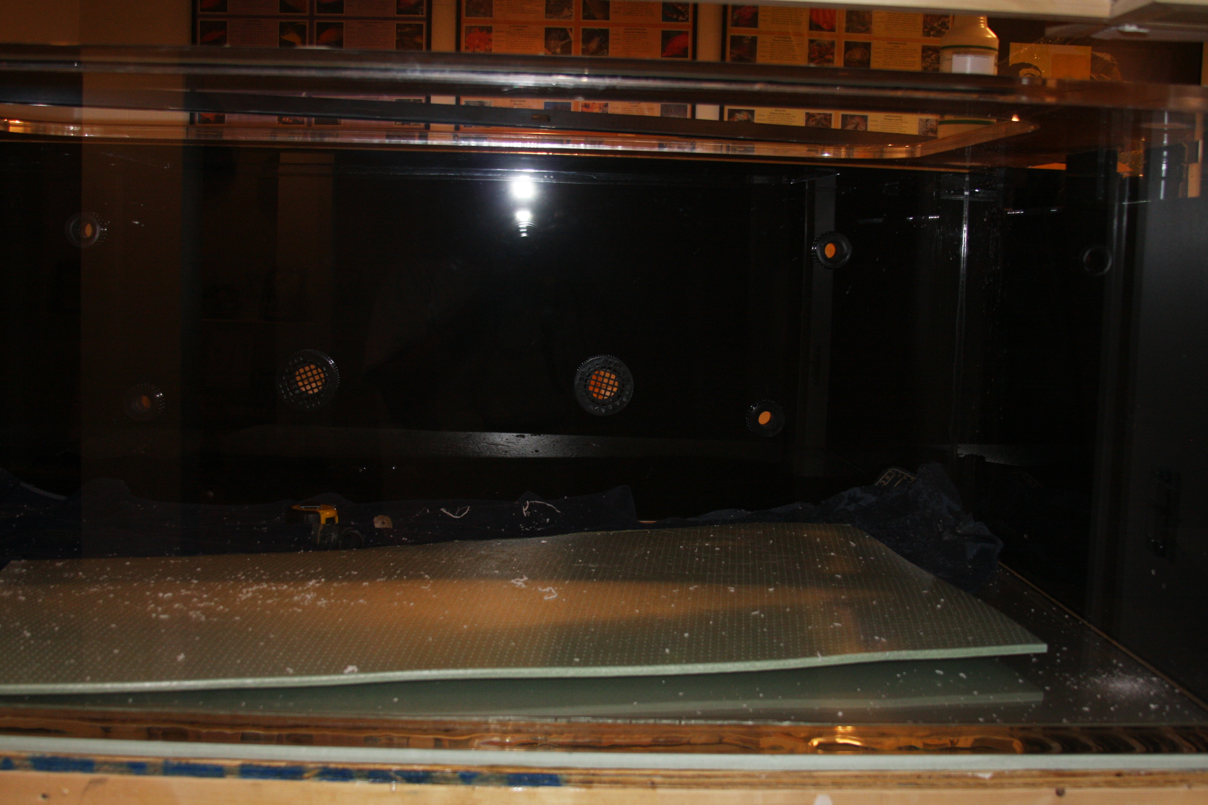
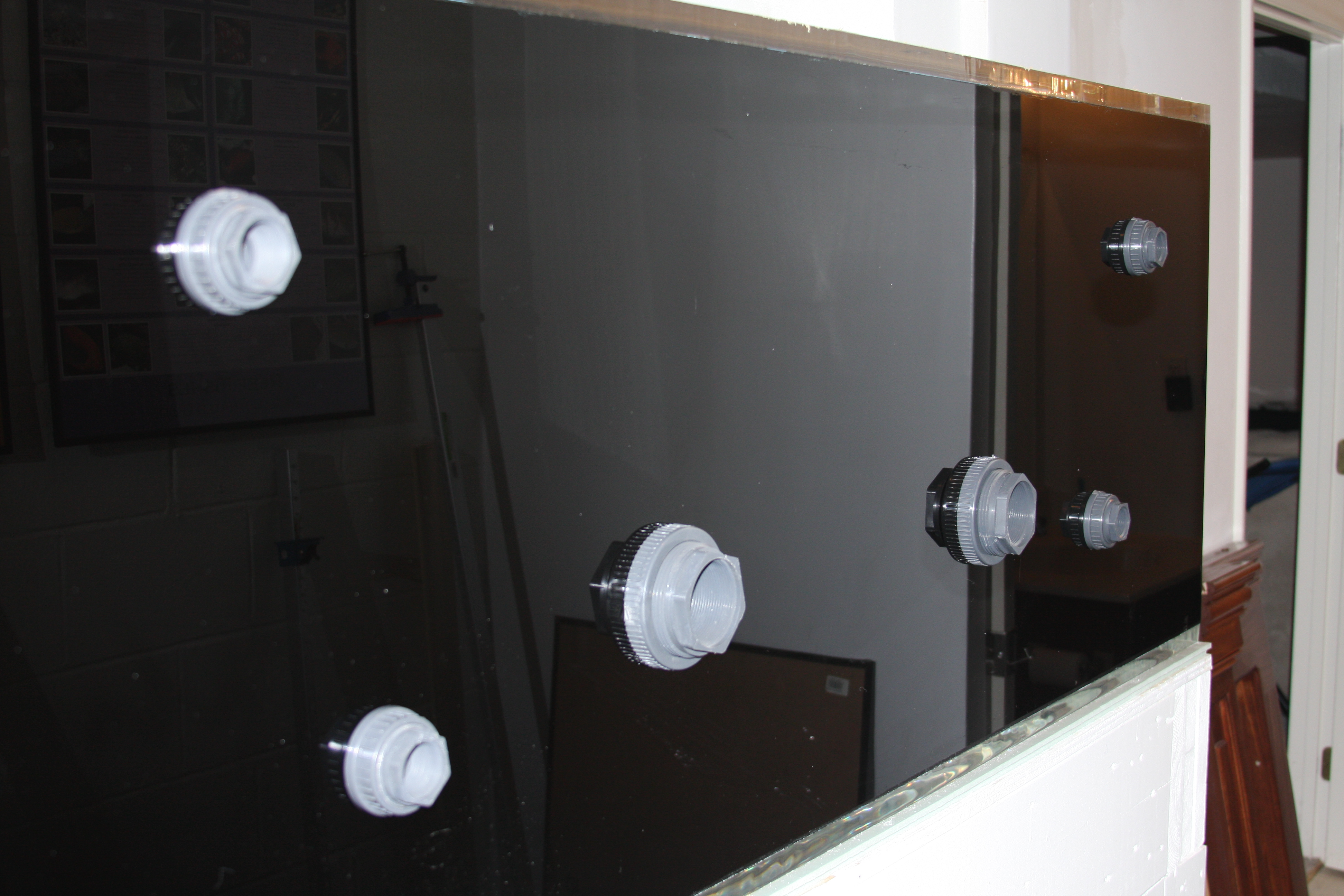
A shot of the tank with the bulkheads drilled for the CL on the back panel.....Hard to tell in the pic, but the bulkheads are painted black......

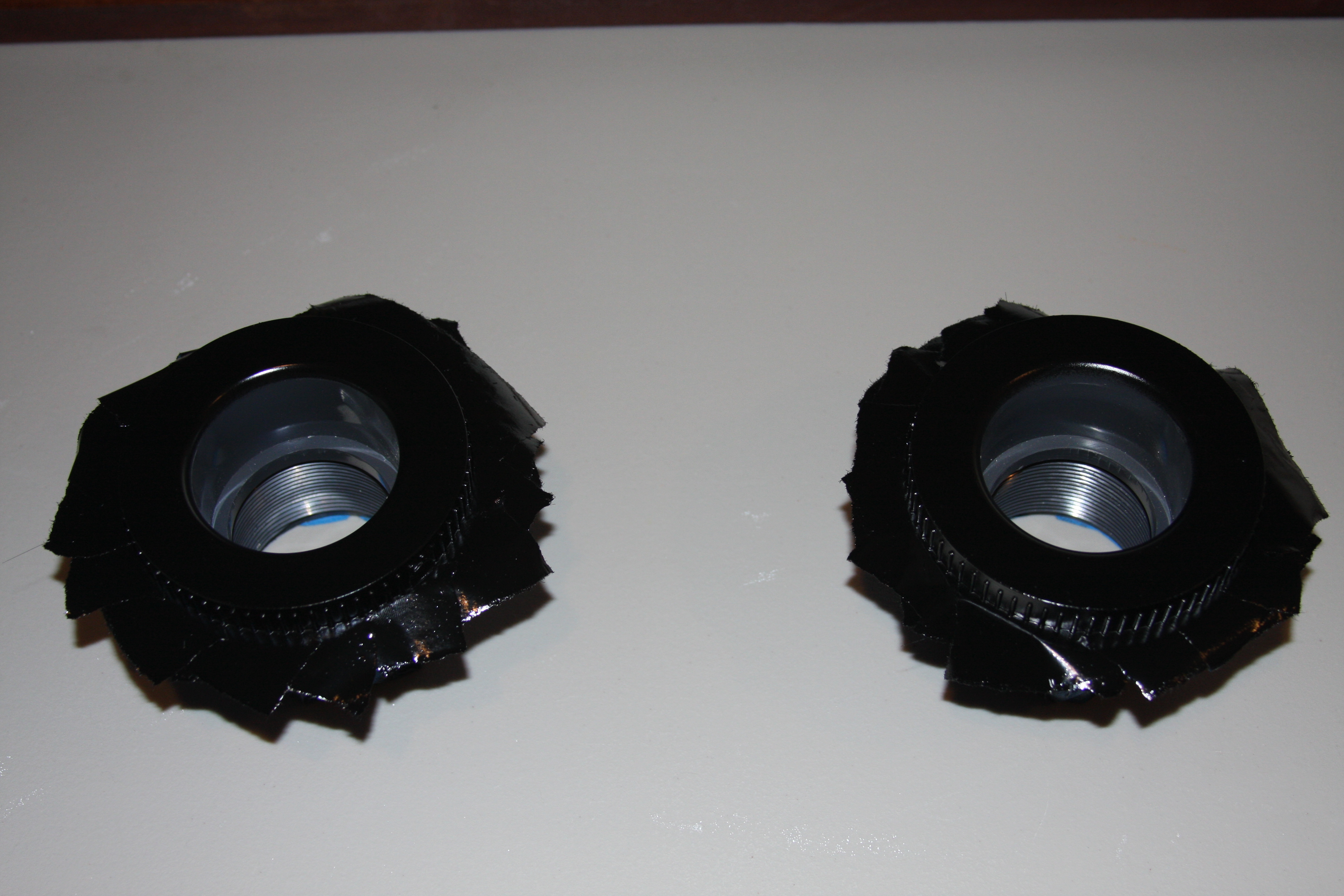
Bulkheads being painted black to blend in with the black acrylic panels.....

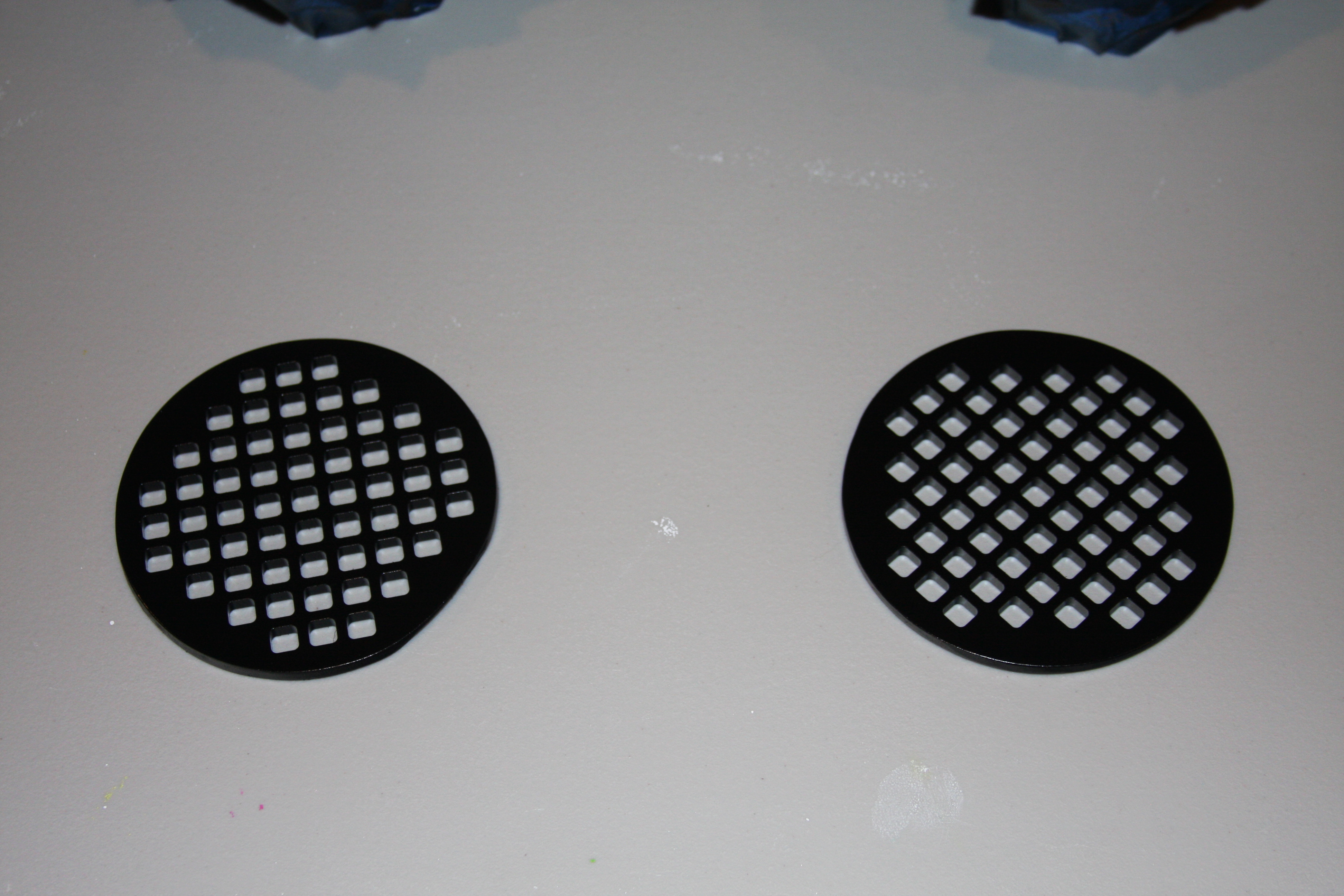
These are the grill covers I made for the 2" drain bulkheads for the CL on the back panel......

I got these from Lowes, and basically cut the top portion off to use for my grating/strainers for my bulkheads.....Just shot them with black paint before attaching them to the bulkheads.....

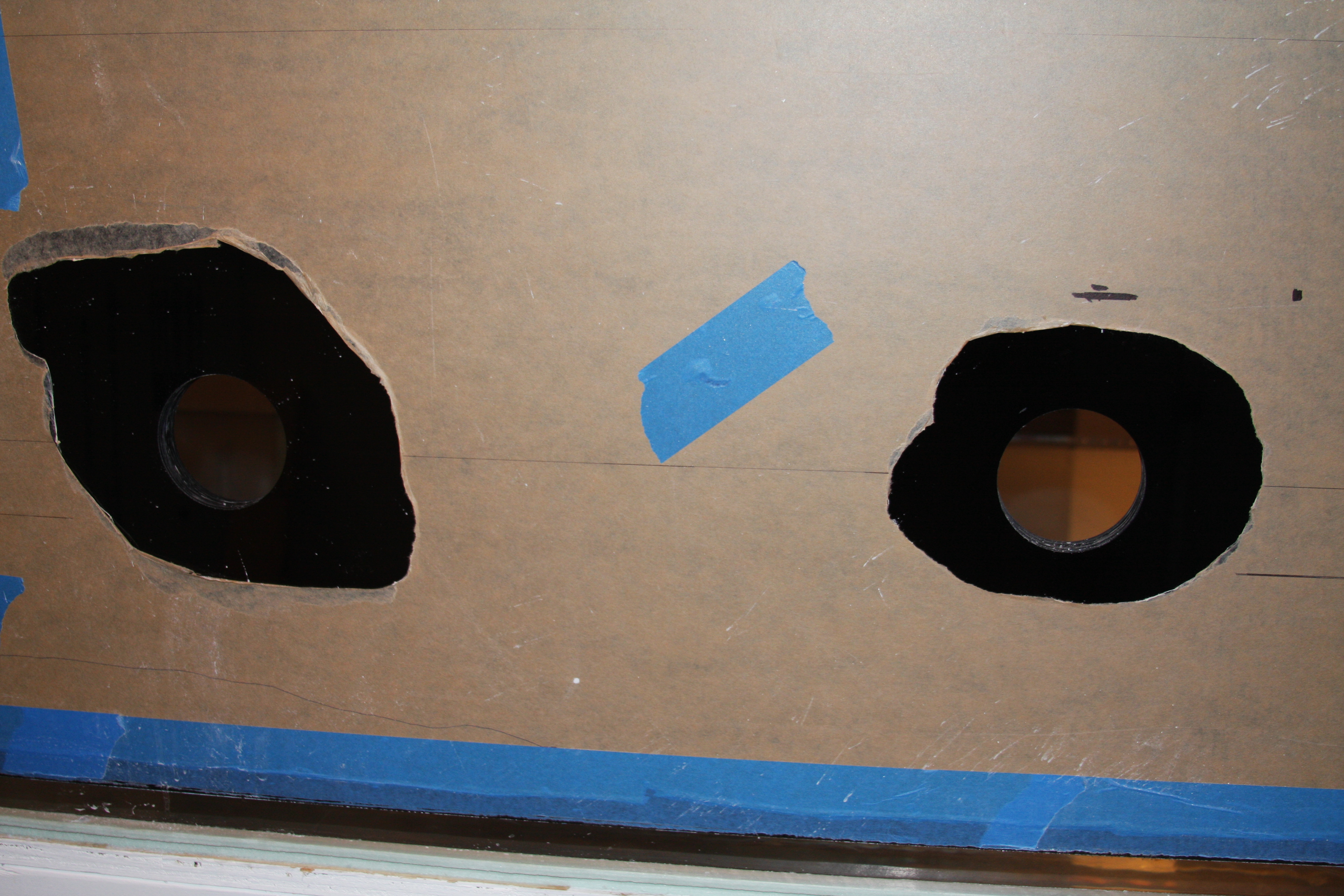
Here's the 2" holes cut into the back panel for the CL.......

Here's a shot of the back of the tank so far.....As you can see I didn't paint this side of the bulkheads.......The 2 bulkheads on either side of the middle bulkheads will have nozzles on them firing towards the side panels.....I've come up with this configuration and hole placement based off of playing around with the Tunzes mounted in a similar location. Actually the Tunzes were mounted a little above the bottom bulkheads and figured if I was 95% pleased with flow at that position, going a hair lower, and higher up in the tank would get me the best of both worlds......
 

acrylic51

Active Member
More updated pics......

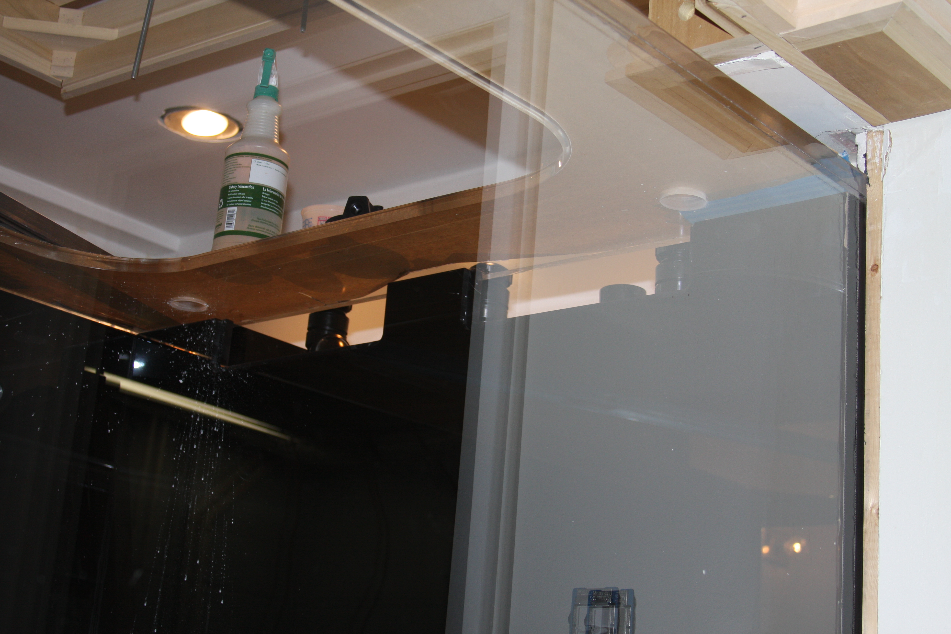
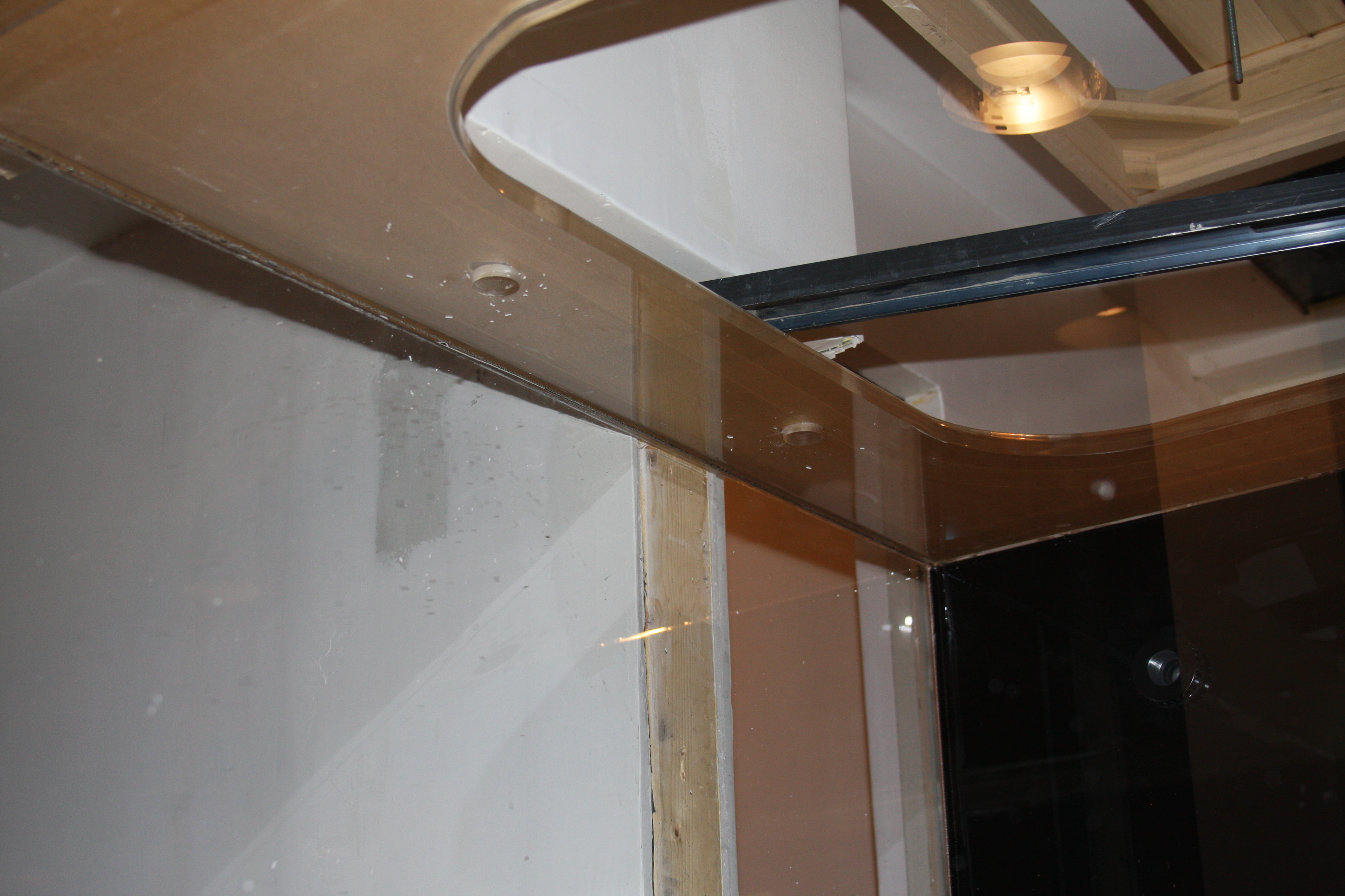
Again not very good pics and kind of dusty/dirty, but it will do for now.....In this pic you can see the 2 return holes I drilled in the euro bracing. These holes will be fitted with bulkheads, and will be 2 of the 4 return lines coming from the sump.....Attached to the bulkheads will be omni flex nozzles which will fire downward towards the bottom of the tank.....

Al, Corey, this was/is the problematic side....As you can see just above the level actually is the wall where the canopy mounts too......These 2 holes are also for return lines from the sump. They are actually drilled smaller than the other side for the fact I have roughly 3" of clearance between top of tank and the down portion of the wall; which won't allow the use of bulkheads and still allow me to get the plumbing to it, so the plan is to open them just a bit more with the sanding drum to allow me to drop the omni flex nozzles down through. Not much worry about them moving since it should be a rather snug fit between the holes and nozzles.....These nozzles will again be dual outlets, but these will agitate the surface and fire directly back towards the overflow box, pushing everything in that direction......

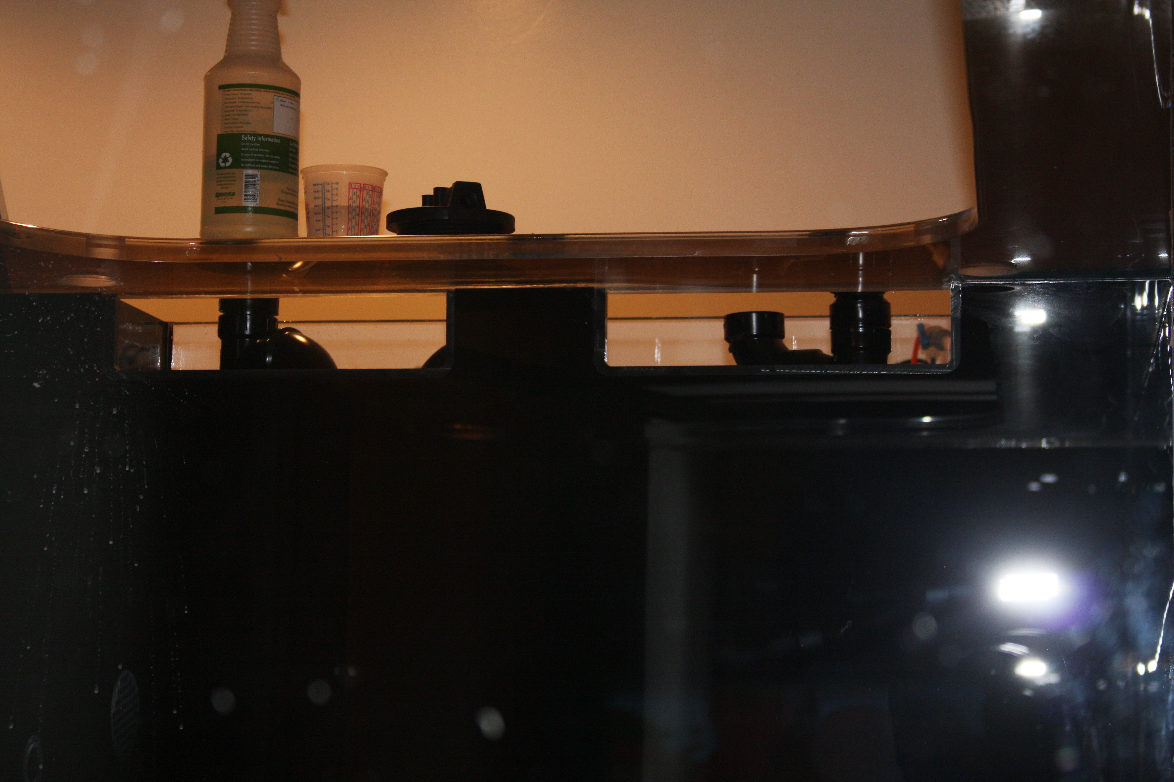
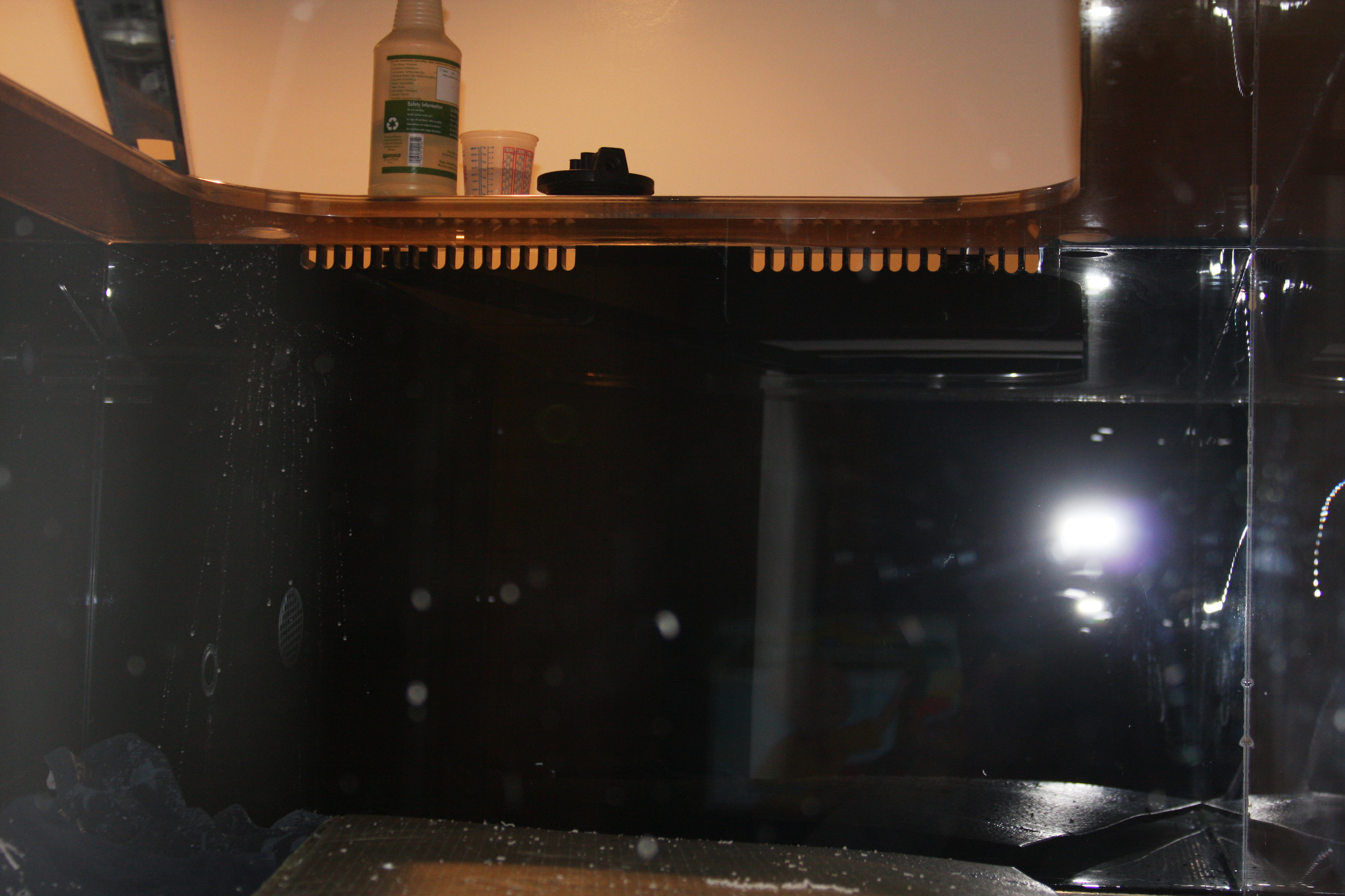
Again sorry for the poor pics, but here's a quick shot from the far end looking back towards the overflow.....You can sorta see some of the stand pipes in the overflow.....They are still longer than needed, and eventually will be cut to proper height. Anyways it gives everyone an idea of the openings to the overflow box with the removable overflow grates in place.

In this pic another shot from the far end, but it shows the removable overflow grates in place.....The grate on the far right is a little snug to get in and out, but I'll wait till it's filled and running to see how the other grate holds...........The return nozzles will not be in front of the grating, but just off to the sides of them........I know that was something you and I had talked about Corey........

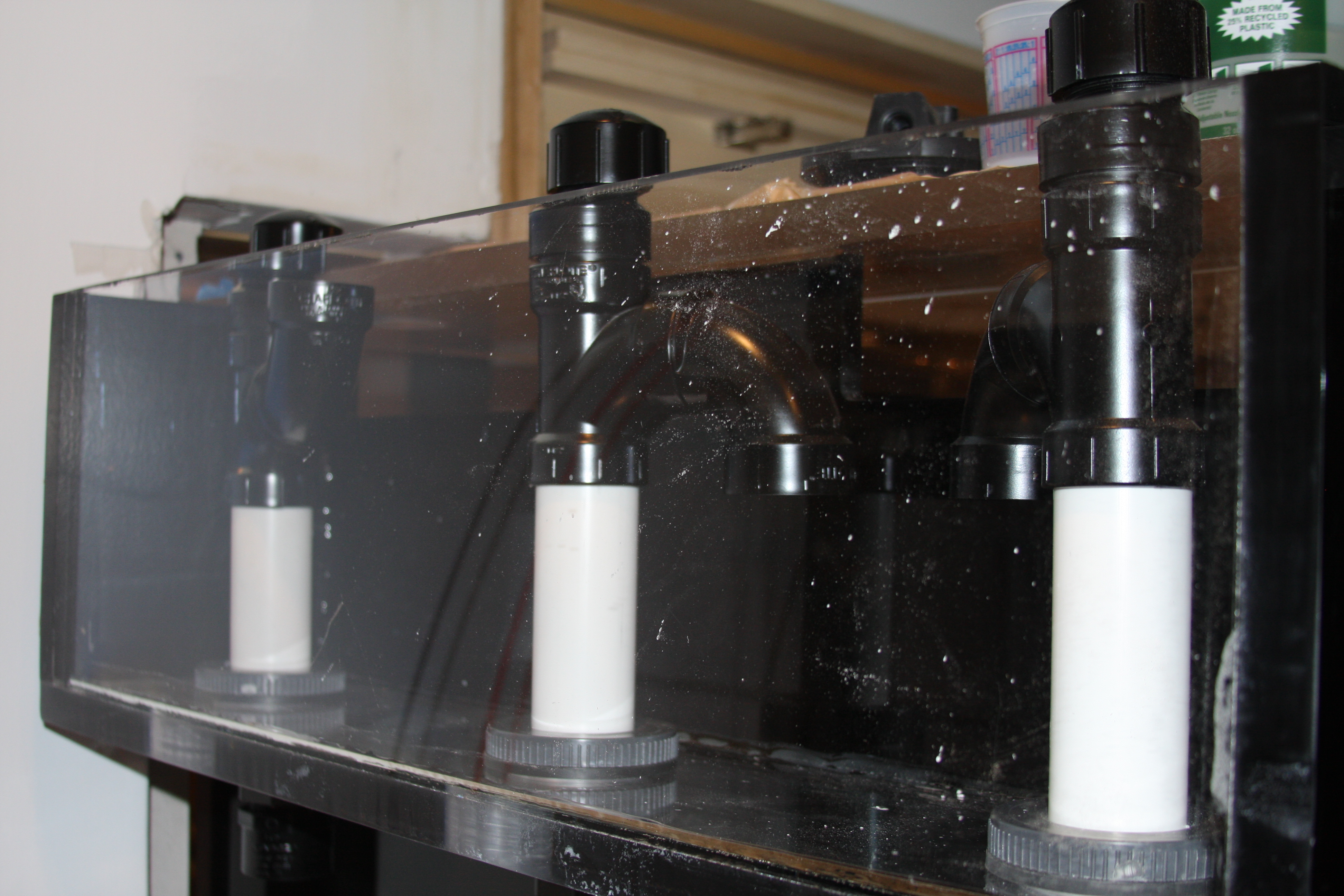
As you can see the overflow is still really dirty/dusty, but a quick shot of the standpipe progress so far......This isn't the traditional standpipe/durso setup. There will be a valve so the siphon can be fine tuned and should be all but dead silent. The far left side will be the emergency drain if need be.....All drain plumbing is 1.5, so is more than enough to carry your average pump......
. They still need cut down to proper height and painted black. I'm particularly anal about plumbing.....Hate seeing primer......I never use the purple primer for that mere reason. Still have to drill the hole in the far right cap for the air line as well.
 

acrylic51

Active Member
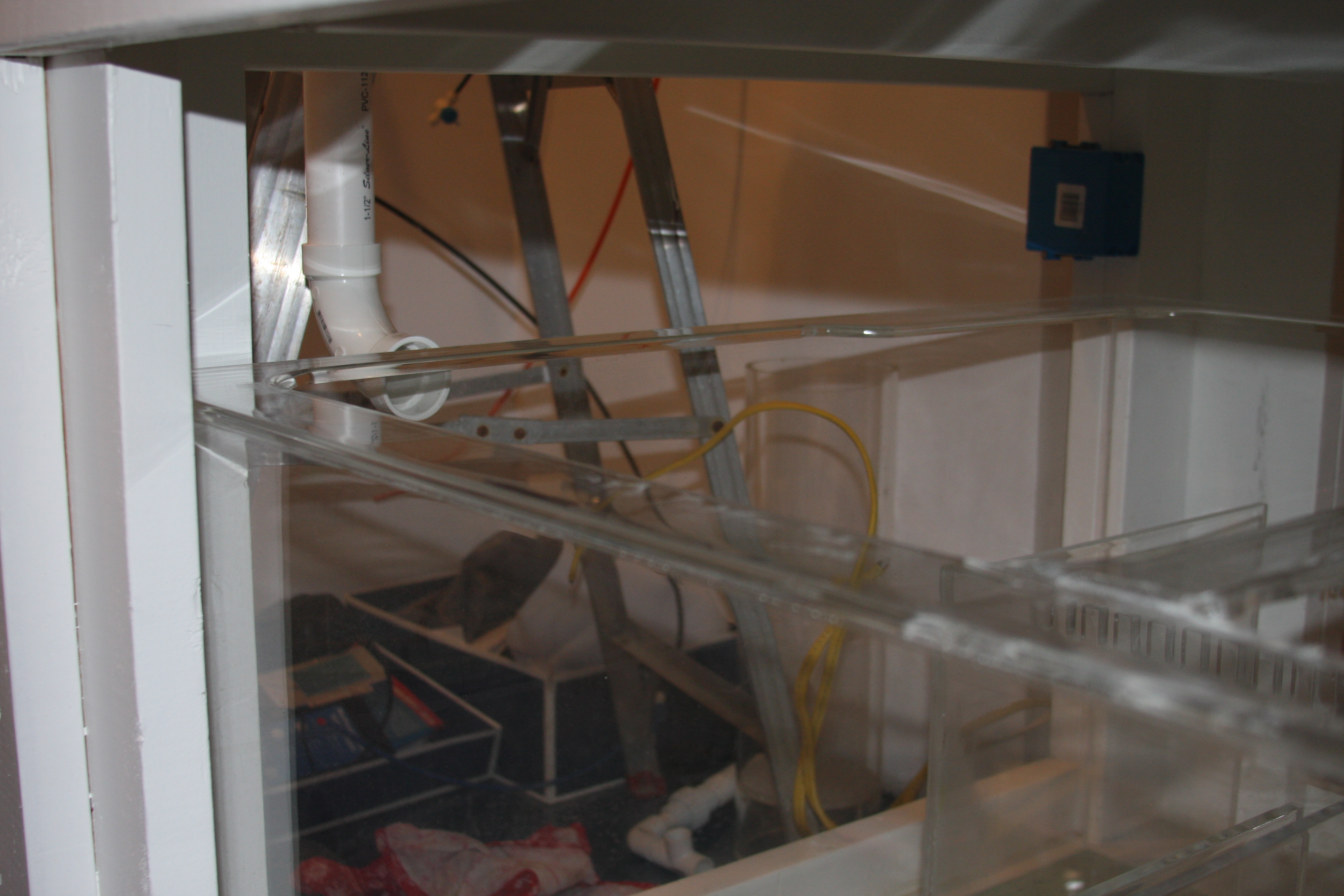
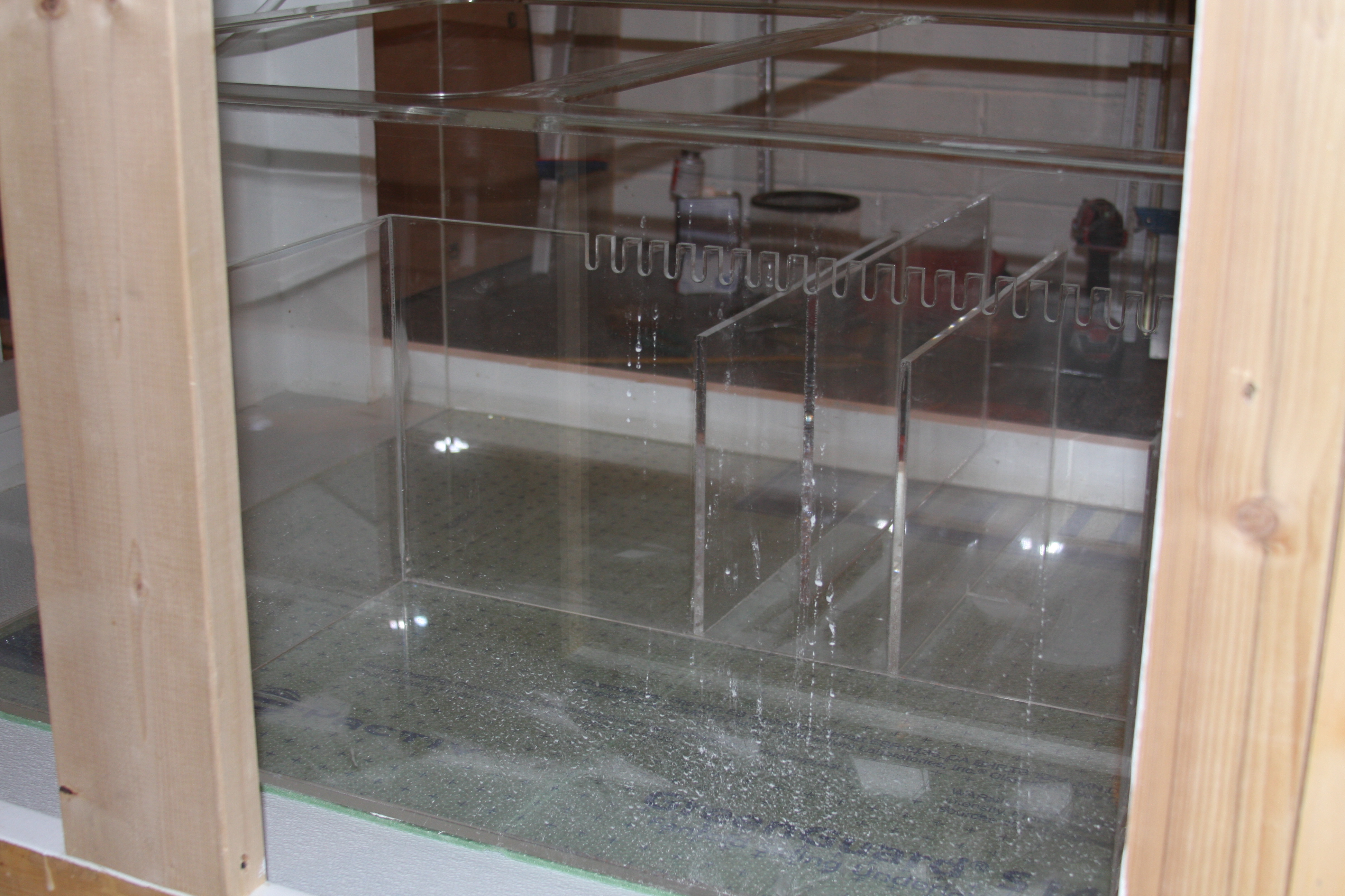
This is a shot of the sump in place, and mocked up PVC from the overflow coming down to the sump......I'm considering putting 3 bulkheads, most likely 2 into the side of sump where you see the elbow roughly at.....This way I can add my bubble tower into place, and have it ready to accommodate a filter sock as well, but will allow me to plumb down pipes into the sump that when I use filter socks they can easily be removed and changed, or if I just run the water into the bubble tower, I can still remove the down pipes if needed.....What's every ones thinking on the bulkhead idea??????
i

Snake this last pic is more for you.......You can see where I had originally intended to run a fuge, but it gives you a general idea on the space I have to run a scrubber....Kind of hard to get a true sense, but I can get better pics for you........
 

acrylic51

Active Member
The holes in the back of the tank......Mine is actually timid compared to some.......
I never promised this would be for the weak stomach......No seriously the (2) center 2" holes are strictly for supplying the pumps with water constantly......You want to "flood" your pumps with water......Those 2 2" bulkheads will feed 2 of the CL pumps.........The other 4 1" holes will be a separate CL system. They will be plumbed to an OceansMotions 4Way, and they will have nozzles angled outward towards the sides of the tank......With them in that position would give me the same flow/motion that I got with the Tunzes more or less.......With the Tunzes I found flow was very good except for on the bottom where it's very important......So I decided to drill 2 holes lower than were the Tunzes were mounted and 2 higher....so flow should be better.....
There will be 2 other separate CL's.......
Earlier on in the thread I had shown what type of flow I was looking for in my system. This is a major area, where I think most of us over look. A lot of us just see water moving an our corals swaying and feel that is adequate.....Technically it's not.....Flow is about keeping detritus suspended in the water column where it can't settle and start decaying, which a lot of us have those issues......With properly planned water flow/movement those particulates are kept suspended in the water column where they can be removed either by the skimmer, filter socks, etc....... That is another reason I have 4 return nozzles from the return pump. The 2 return nozzles on the overflow end will again be split into 2 for a total of 4.....The flow from these nozzles will be forced downward towards the bottom of the tank.......By forcing the water down I'm trying to force it down and deflect off the bottom and out and across the length of the tank......
As Corey pointed out, you loose some, so to combat this issue through extensive discussion with Paul from OM.....There will be 8 nozzles in the bottom of the tank.......
These nozzles will take/force the water coming from the return lines down along and across the bottom of the tank........again creating a circular motion length wise of the tank.....The object is to move the water in the direction of the overflow so particulates can be removed from the system......With that being said, the very last nozzles on the bottom of the tank on the far end away from the overflow will be pointed towards the water surface at roughly a 45 degree angle......The purpose for this is all the water/particulates, and what nots being forced across the bottom portion of the tank, will then be forced upwards towards the top of the water surface. At this point, this is where the other 2 return pump nozzles come into play.......These lines again will be split into 4 utilizing the omni nozzles......They will then force the water being brought up from the bottom of the tank, across the water surface forcing it to the overflow.....Basically what a lot of us do is somewhat incorrect. We chance that it will eventually make it to the overflow box.......Stop and look at our systems....Most of us just chance water making it back.......Or we see matter just haphazardly floating across the water surface. With the nozzles blowing towards the overflow box, we are forcing/guiding everything in that direction......
With that long explanation, you can kind of gather that there will be a circular water flow the length of the tank from top to bottom back to the top......And there will be a circular pattern basically from the back to the sides, along the front, around the sides, and to the back again...........
Currently I'm looking at options to shut down 1 or 2 of the CL's during the night time hours to simulate different tides......Also another option would not to totally shut the CL's down, but to plumb smaller pumps something on the line of a Mag Drive into the CL's, and during this night time tidal change, the Reeflo pumps would be off but the CL's would still be functioning, but will a rather small flow amount........Still in planning stages though.....
 

snakeblitz33

Well-Known Member
Hey man,
Everything looks like it's coming together. I really like your return lines and your double closed loop design. I also like the idea of following the tides, many people don't do that, but I like it. :D
As far as that pic goes, I'de have to have a couple of pics and the dimensions of the fuge area that you have. From the looks of it, that eurobrace is really cramping it right there - but it might just be the angle that the pic was taken. Remember that scrubber screens can't be submerged... So, we'll have to figure out how to put at least four double lit screens over the top of that area.I would need the dimensions of the area that you are putting it in and the height between the surface of the water and the top of the stand ... clearance. We'll go from there.
I have a really, really good idea and design for multiple screens that I'll share with you, as long as the dimensions work. lol, I think it's funny how I've become the "local scrubber expert." hah
 

acrylic51

Active Member
Thanks Al!!!!! Honestly really been slacking though.
Snake I will try to get some better pics of the area. Actually have 2 areas that are a possibility, but upfront I'm not looking to totally run or rely on the scrubber for my filtration. As I had stated earlier I like redundancy in a system, so the setup will employ an adequately sized skimmer to handle the total water volume of the entire system. With that said I want/plan to run them side by side; knowingly that neither would/will run at full efficiency.
The area that was original designed or built for the fuge is the center area shown in the pic. That area measures 30"Lx 16"Wx15"H to bottom of teeth cut into the panel. The distance between the bottom of the teeth and stand is roughly 17". An issue I can see using this area I the cross bracing on the sump. The euro bracing itself around the perimeter is only 2".
The other area of possible use is on the back side of my sump, which is my return area. I made this area huge!!!! Tho area measures 30"x36". The water depth would beat 10". The height available then would roughly be 26". My major concern or issues with employing a scrubber I splashing, salt spray/creep, and micro bubbles in my return area. Curious to see what you come up with????
Another question; since it probably got lost in my earlier postings, but everyone's thoughts/opinions on drilling sump with bulkheads to bring water into the sump rather than draping the lines over the edge and then into the sump??
 

2quills

Well-Known Member
Looks good. You could always run a scrubber externaly by building something like Santa Monica or floyds design and leave yourself room under the stand for all that plumbing.
 
Top