415 Gallon Plywood Tank Build

acrylic51

Active Member
Some Updates!!!!!!!
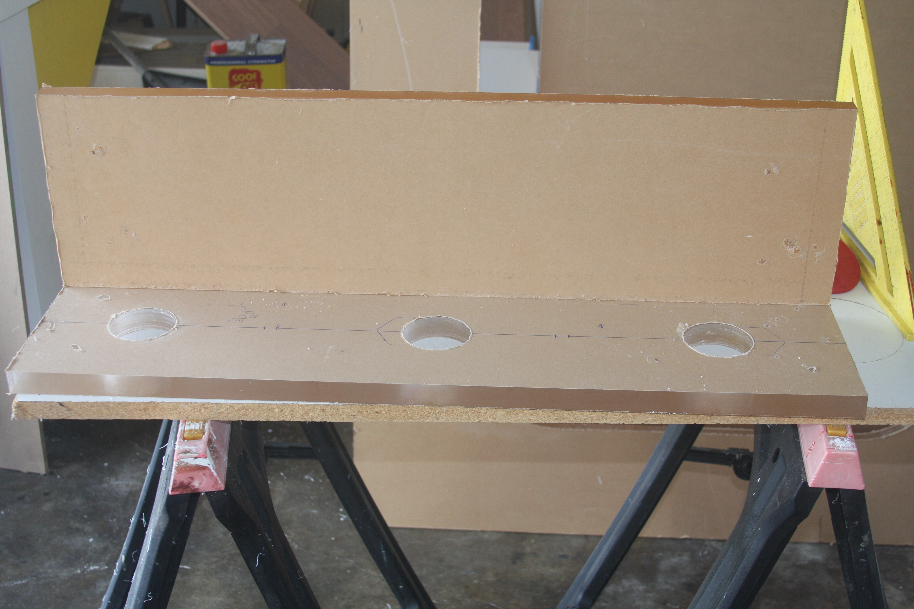
After figuring out what was going on with the edges not wanting to take glue, and the use of the hand held planer this is the end result making a pass over the edges......Corey it's pretty easy to prep your edges this way. The only thing I'd recommend is guides on both sides of the work piece to make sure you don't teeter either way...... You'll also see that I also cut the holes for the bulkheads in the overflow....I will be utilizing BeanAnimals design, and the holes are cut for sched 80 1.5 bulkheads.....
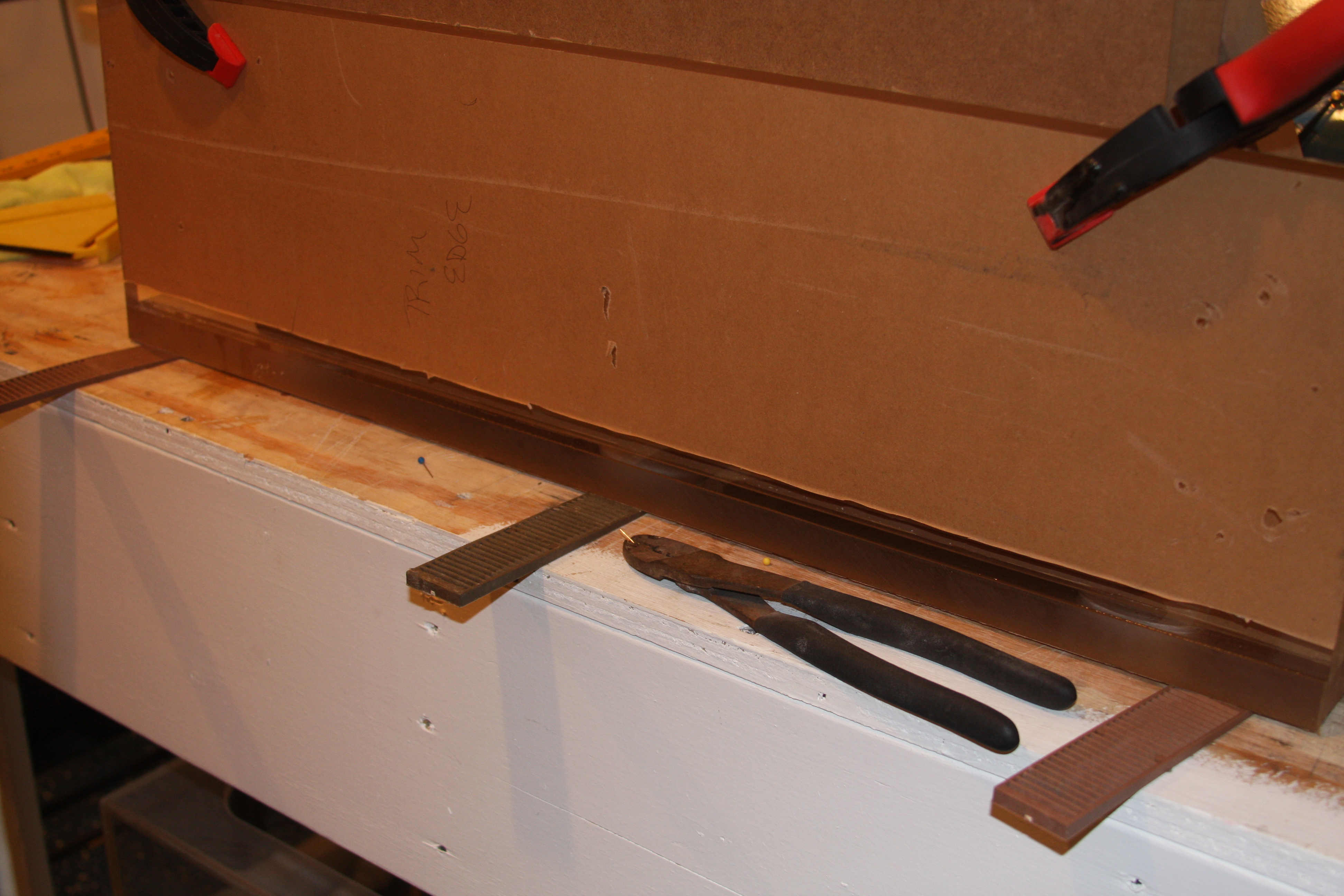
Her's is the piece mocked up, and pins pulled......I had mentioned to Corey that I switched from twisty ties to straight pins, out of my daughters sewing kit.....Works great, just the little ball heads on the pins like to come off occasionally, so I keep the piers handy and you can see 1 of the pins sticking in the pliers......
 

acrylic51

Active Member
Now for some real meat and potatoes.....The construction of the "new" tank begins......My buddy is trying to convince me to cut the other tank down and use as a coral or QT tank in the fish room, or better yet let him have it.........


Sorry about the poor pics!!!!! Actually the tank is being built in the fish room, so my wife doesn't complain to much about the clutter....As I mentioned before I have to decide what to do with the other tank sitting in the family room......This is the first panel glued into place......Sorry for the acrylic panel obstructing the view...

Right end panel glued into place.....Actually hard getting pics of the thing due to size, and space available to shoot pics......This is the end of the tank where the overflow will be installed externally....See Corey and Al.....Using the Denatured Alcohol now!!!!!!
 

acrylic51

Active Member
Last bit of update!!!!!!! Here's a complete shot of the work so far with both panels installed....Again sorry for poor pic angles....

Your looking at the end panel where the external overflow box will be mounted.......I need to get the assembled portion down so I can swipe the edges of the vertical pieces 1 last time before gluing the front viewing panel......I would sit it on the stand, but with the light rack mounted, the tank is actually to tall to sit on it's face.....Will probably have to take the light rack down for the time being and lay the front panel on the stand and then con a friend to help me lift and flip the assembled portion over onto the viewing panel and get everything lined up to glue the other panel. Not sure at this point if I want to glue just 1 end and wait till the next day or do both on the same day?????? I've actually been quite patient with giving each glue joint 24hrs before moving the piece.......

This is the top of the tank (eurobracing) already cut out and prepped. Not worried to much about the edges of the panel since it's over sized and will be trimmed flush once it's glued into place.....I actually did prep the inside of the cutouts with wet/dry sandpaper for the mere fact I won't be gluing anything to the inside surface and want an ultra smooth finish for when I take the roundover bit to ease the edge of the panel inside.......Going to be using a 3/4" roundover bit for the task.....
 

acrylic51

Active Member
Alright all you tech wizards and fabricators out there......Need some input.....Getting ready to start fabbing up the overflow box inside the tank. Reasoning behind the slim box inside is to actually raise the water level a bit.
Curious as to if I use a 1" opening for the "slot" and return pump choice will be the Hybrid Reeflo Snapper/Dart. If I run the pump a little more wide open how much of a rise in the 1" opening could I expect?
 

al&burke

Active Member
The rise will only depend on the drain size. You will only get a rise as you approach the maximum draining capacity of your drain (which in turn turns the turbine, LOL) and you know what will happen if you get past the draining capacity. The slots area needs to be close to but larger than the area of the drain it self, it is like a differential equation to determine the rise in the slot which is directly proportional to the drain size. Shawn if you give me the size of the slots the number of slots and the size of your drain I will draw something up and try to figure out the height of the water in the slot. And a few other calculations. Also need the center-line distance of the drain.
 

2quills

Well-Known Member
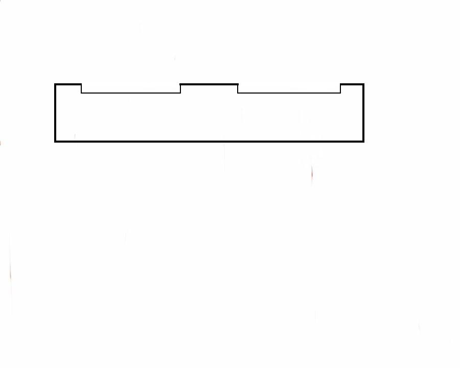
Well depending on what Al comes up with for his calculations and drawings. I was thinking that since you mentioned on the phone that you'd like to end up with a water line approximately 1" below the top of the tank you could do a design similar to this which would be equal to the size of the slots on the side panel of the tank. You said that the slots on the panel are 1-1/4" wide x 12" long. I'm thinking the rise would be pretty minimal if you went that way. 1/4" maybe, but that's just a guess.
This would be the front of the internal over flow. Unless of corse you a joint that you can glue across the entire top of the overflow to the brace then in that case you'd have to do slots.
 

scott t

Active Member
Hey Shawn, everything is looking good see you are still hard at work on your project, can not wait to see the finished product. Well I have started my tank now its up and cycling. here is a link to my thread https://forums.saltwaterfish.com/forum/thread/382874/my-tank-build-diary/520#post_3405359 Thanks for all your help =)
 

acrylic51

Active Member
We need to have a direct line sorta like the bat phone Corey!!!!!
That's pretty close to how the outer panel is cut, and started drawing out what you drew on the acrylic when we started talking.....
 

acrylic51

Active Member
Quote:
Originally Posted by Scott T http:///forum/thread/376802/415-gallon-plywood-tank-build/980#post_3405380
Hey Shawn, everything is looking good see you are still hard at work on your project, can not wait to see the finished product. Well I have started my tank now its up and cycling. here is a link to my thread https://forums.saltwaterfish.com/forum/thread/382874/my-tank-build-diary/520#post_3405359 Thanks for all your help =)
Thanks Scott!!!!!! Also Thank You for the PM. I will have to bring myself back up to speed over there on your thread!!!!!! Congrats!!!!!
Quote:
Originally Posted by 2Quills http:///forum/thread/376802/415-gallon-plywood-tank-build/980#post_3405371
Well depending on what Al comes up with for his calculations and drawings. I was thinking that since you mentioned on the phone that you'd like to end up with a water line approximately 1" below the top of the tank you could do a design similar to this which would be equal to the size of the slots on the side panel of the tank. You said that the slots on the panel are 1-1/4" wide x 12" long. I'm thinking the rise would be pretty minimal if you went that way. 1/4" maybe, but that's just a guess.
This would be the front of the internal over flow. Unless of corse you a joint that you can glue across the entire top of the overflow to the brace then in that case you'd have to do slots.

Corey not sure what you meant above in the red??????
Quote:
Originally Posted by Al&Burke
http:///forum/thread/376802/415-gallon-plywood-tank-build/980#post_3405355
The rise will only depend on the drain size. You will only get a rise as you approach the maximum draining capacity of your drain (which in turn turns the turbine, LOL) and you know what will happen if you get past the draining capacity. The slots area needs to be close to but larger than the area of the drain it self, it is like a differential equation to determine the rise in the slot which is directly proportional to the drain size. Shawn if you give me the size of the slots the number of slots and the size of your drain I will draw something up and try to figure out the height of the water in the slot. And a few other calculations. Also need the center-line distance of the drain.
Thanks Al.....There are 2 slot on the panel.......Each slot is 12"L x 1.25"W......Between each slot is a 6" solid area for structure to tie into the eurobracing......I'm going with the BeanAnimal overflow design which incorporate 3 drains.....Not all 3 are utilized where 1 is a backup. Drain size is 1.50. There really isn't a great increase going any bigger than 1.50. Should also mention return pump will be the Hybrid Reeflo Snapper/Dart, but will be on a manifold to feed other components as well.
Not sure what you mean by what I have highlighted in red?????
 

2quills

Well-Known Member
Just meant that if you were looking for one solid joint across the top of the o/f that you could do slots just like you did with the side panel for one continuous joint on top. I think if it were my choice, the idea in the drawing seems like it would be easier to do. I know you were talking about the overflow adding reinforcement to the side panel. But think you'd be fine either way.
 

acrylic51

Active Member
Thanks Corey!!!!! Actually both ways are easy IMO to cut......The way your drew up would be actually quicker and easier to cut.....I did the back panel the other way, but wasn't hard just more time consuming. Actually even with the panel cut out like I did there isn't the flex I thought there'd be in the piece....Actually shocked/surprised how strong the material is......I did post a pic of the eurobracing complete????? The eurobracing is 1" thick and is 8 1/2" wide all the way around, so seriously I doubt anything is going anywhere!!!!!
 

2quills

Well-Known Member
Yeah I was thinking you'd be good either way. This way does seem slightly easier to cut and easier to keep the water level where you're looking to have it without question of how little or much it's going to rise and not have to worry. Cause once it's in there it would be harder to change as you well know.
 

al&burke

Active Member
Quote:
Originally Posted by acrylic51 http:///forum/thread/376802/415-gallon-plywood-tank-build/980#post_3405394
Thanks Scott!!!!!! Also Thank You for the PM. I will have to bring myself back up to speed over there on your thread!!!!!! Congrats!!!!!
Corey not sure what you meant above in the red??????
Thanks Al.....There are 2 slot on the panel.......Each slot is 12"L x 1.25"W......Between each slot is a 6" solid area for structure to tie into the eurobracing......I'm going with the BeanAnimal overflow design which incorporate 3 drains.....Not all 3 are utilized where 1 is a backup. Drain size is 1.50. There really isn't a great increase going any bigger than 1.50. Should also mention return pump will be the Hybrid Reeflo Snapper/Dart, but will be on a manifold to feed other components as well.
Not sure what you mean by what I have highlighted in red?????
The distance from the top of the tank to the center of the slot. I am a bit confused are you going to have an internal overflow box? Need the size of that as well if you are (including size of teeth)
Edit: sorry Shawn for some reason the drawing above was not up when I read this - I understand now (me thinks)
 

2quills

Well-Known Member
Think he is doing both Al. External box will have plumbing and the internal strictly to set the water level.
 

acrylic51

Active Member
Al Corey is correct..The internal box is more to preset the water height a little higher. The inner box will contain no plumbing. All the plumbing will actually be in the external overflow box.
The top of the slots are 1 1/4" from the top of the panel. Off the top of my head; not at home at the moment so don't have exact measurements, but I think the slots are 1 1/4" - 1 1/2" wide; so let assume the middle of the slot is at 2"!!!!! The size of the inner box Corey drew up would be nothing more than a damn to raise the water height. The dimensions roughly would roughly be that a piece would come out from the panel roughly 2 1//2" and the other piece attached going vertical roughly 4". We had tossed around the idea o cutting the inner box slot about the height of the top of the opening on the outer panel!!!! Hopefully you. Understand what I'm saying and not confusing you to much???
 

acrylic51

Active Member
Sorry for the extra post Al, but on the internal box it will be a straight slot cut. Teeth aren't an issue to cut, but does reduce flow and does cause an increase in noise. Not that noise is a real issue, but want it as quiet as possible. The NO teeth issue ha more to do with flow than anything!!!!! If I were to cut teeth minimum would be 3/4" wide.
 

2quills

Well-Known Member
Quote:
Originally Posted by acrylic51 http:///forum/thread/376802/415-gallon-plywood-tank-build/980#post_3405480
Sorry for the extra post Al, but on the internal box it will be a straight slot cut. Teeth aren't an issue to cut, but does reduce flow and does cause an increase in noise. Not that noise is a real issue, but want it as quiet as possible. The NO teeth issue ha more to do with flow than anything!!!!! If I were to cut teeth minimum would be 3/4" wide.
If you went toofless you could go around the back side of the slots with a roundover bit. Most of the water should flow easily over the back of the slots and mostly run strait down the piece. Less splashing, less noise...know what I mean?
 

acrylic51

Active Member
i'm following you about easing the backside of the cut outs!!!! Do you think 2" is to small of a standout from the back panel??
Where you at Al??? I know you have something up your sleeve?!?!?!
 
Top