415 Gallon Plywood Tank Build

acrylic51

Active Member
Ok guys!!!!!! Had a little time to think it over, and I fully understand the plan I threw up there would be hard to replicate, but as it was pointed out I think most of the time we honestly overlook things such as water flow within the system.....Again as we all know and understand an empty will create a flow pattern differently than a tank with rock work. We also know that as corals grow in that again the water flow patter will change, and decrease. My main major goal was to keep the tank as clean as possible without clutter from PH's.
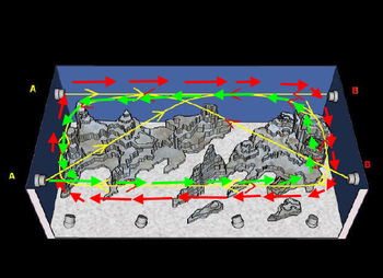
I like the idea of the flow pattern here, and this I think wouldn't be affected much by rock work and could easily be adjusted to work around the rock work. The rock work shown in the pic is similar to the 2 islands I'd like to create, but not exact.....I do want to leave the middle open somewhat for a good swim area. The real issue with this style plumbing is the bulkhead on the left front of the side viewing panel....There is NO Way I can drill that far forward on the tank...... Again I fully understand your analogy Corey when you reference a tennis ball hitting a wall vs. water hitting a glass panel.....You might not get the full inertia of water, but a portion of that flow being bounced and directed is all were looking for to a certain degree.....You figure a wave is created in 1 shot, but it's the continual movement back and forth that creates that wave to increase energy, strength, and thereby becoming larger.....

This is the area where I think if the bulkheads were drilling in the eurobracing, and again keep in mind that I'm not using standard PVC to direct flow.....I'm considering using the Omni Nozzles which give me a bit more control and angling ability.....Something similar to loc line. I do agree that with the bulkheads mounted in the bottom near the front panel wouldn't give me what I'm after, but think possibly I would get more of the "roll" affect from mounting in the eurobracing, because I could fire them at a sharp angle downward. A problem could arise as mentioned early creating a sand storm.
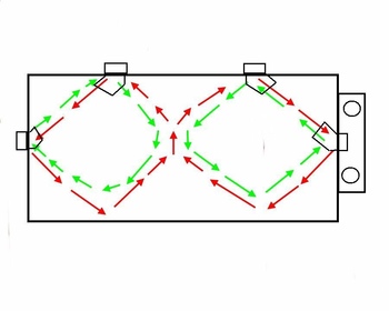
This image right here I'm liking, but again I still think the flow is lacking.......Lacking IMO because I'm still not pulling water from top to bottom, which even looking over the OM forum is something Paul likes to see and thinks as well that it benefits a system.....I think this could be accomplished a couple different ways.....I could be done with a OM 4Way or 2 OM Squirts.....The Squirts don't handle as much pump pressure though.....
The only thing I wonder is how effective it will be????? You would almost have to run 2 OM 4Ways, and have them and the pumps plugged in a controller, and have the controller run 1 setup in 1 direction for "X" amount of time, and then shut that system down and fire the other system and run the opposite direction. Any thoughts on that?
This is something Paul usually recommends......
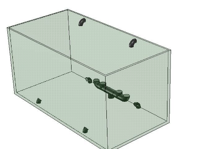
The top 2 nozzles on the back wall are the returns from the sump......The manifold on the bottom back wall is the drain for the CL, and as you can see he has done 2 mounted in the bottom near the front panel aimed up and back and 2 along the back wall aimed forward to achieve the roll...??????
 

2quills

Well-Known Member
I certainly think that set up would achieve a roll more efficiently, especially since it is using 3 points of flow to help it. But if it gets blocked by rock work than it's anybodies guess. You could do something like that and raise the rock up on shelves...that might work.
A couple more ideas. The omni nozzles mounted on the back through the brace. Allowing many different configurations as you mentioned with their flexibility.

Couple that maybe with a second OM 4 way and have 4 bulkheads mounted on the bottom. The ones in the back corners would be easy to hide. Just have to get clever on the front corners. Kick them on during and after feedings to keep food suspended from off the bottom. The combined flows from each side meeting in the middle, crashing and flowing upwards should be good for that.
 

acrylic51

Active Member
I guess I should have explained a little better......I was under the assumption we were including the returns from the sump......In your first sketch in the above post Corey possibly the OM revs would be a better option or choice. I only say this is because you can make them rotate with water pressure.....When water pressure is applied to the "rev" it drops down below the water line and fires.....when water pressure is taken away it pops back up out of view somewhat, and the next time pressure is applied to the "rev" it drops down and indexes; rotates so the nozzles are spraying a different direction each time pressure is applied to that "rev".

Currently I have a couple of these....Not sure how many I have laying around, but it kind of gives you an idea of what I'm meaning when I say they would drop down and fire, and pop up and back down rotating a bit......The rev would fire from all 3 ports.....so basically the firing points would always be changing.....This could be benefical up to on the back eurobracing?????
I'm not quite sure it would be super hard to hide the omni nozzles.......I wouldn't have to use the 2-3 segmented ones.....They have a couple....I think the worse part is they are a dark gray in color.....I would need to make sure they are above the sandbed, so not to create a sand storm....


acrylic51

Active Member
I had thought about using those movable jets for the returns......I can't find any schedule 80 though......so I kinda threw that idea to the way side.
 

al&burke

Active Member
I thought that schedule 40 fitting could be used with schedule 80 - the outside diameter is the same for both schedules.????
 

acrylic51

Active Member
Quote:
Originally Posted by Al&Burke http:///t/376802/415-gallon-plywood-tank-build/1100#post_3412687
I thought that schedule 40 fitting could be used with schedule 80 - the outside diameter is the same for both schedules.????
Sorry Al!!!!! I was referring to schedule 80 bulkheads.....I won't put a schedule 40 in a tank if I can avoid it.....When you hold the 2 in your hand you have a bit more confidence....Even comparing the 2 gaskets is shameful IMO.....
They say they are the same diameter outside sched 40 sched 80, but I mocked up sched 40 pipe in my sched 80 bulkhead for the drains in the overflow and the sched 40 is sloppy in the bulkhead????
 

al&burke

Active Member
Gotch yah - I understand - you are a perfectionist and I admire that - this is like the iron chef America - Very well done acrylics LOL
 
Amazing build! I cant wait to see this done! A quick question. How do you keep all your water from siphoning back and overflowing your sump with the returns on the bottom of the tank? I have always been curious how people do this.
 

acrylic51

Active Member
The bulkheads on the bottom of the tank are for a CL(closed loop). The CL system is separate from the sump return and even when power is cut off the water stays contained in the plumbing of the CL.
 

acrylic51

Active Member
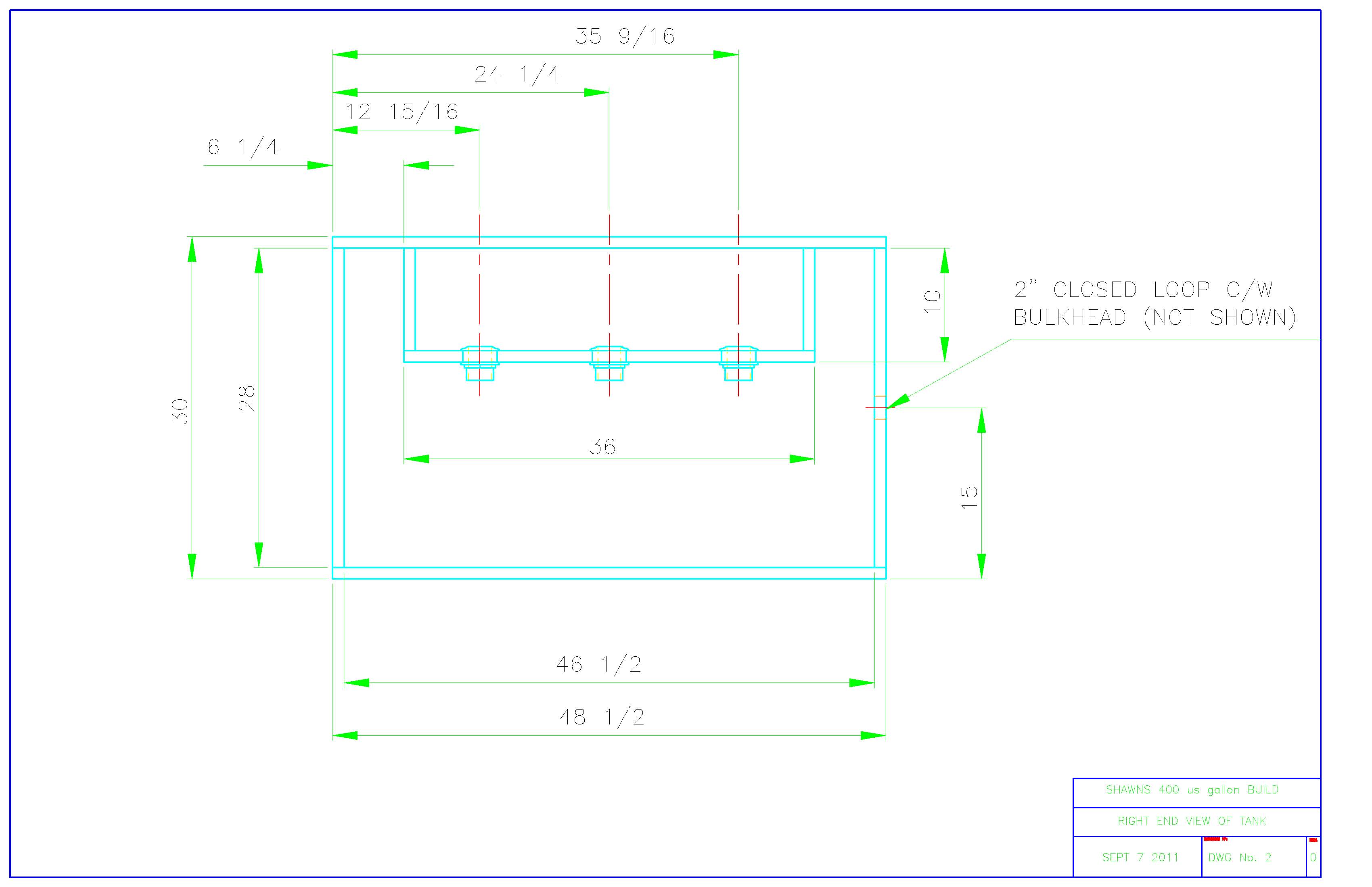
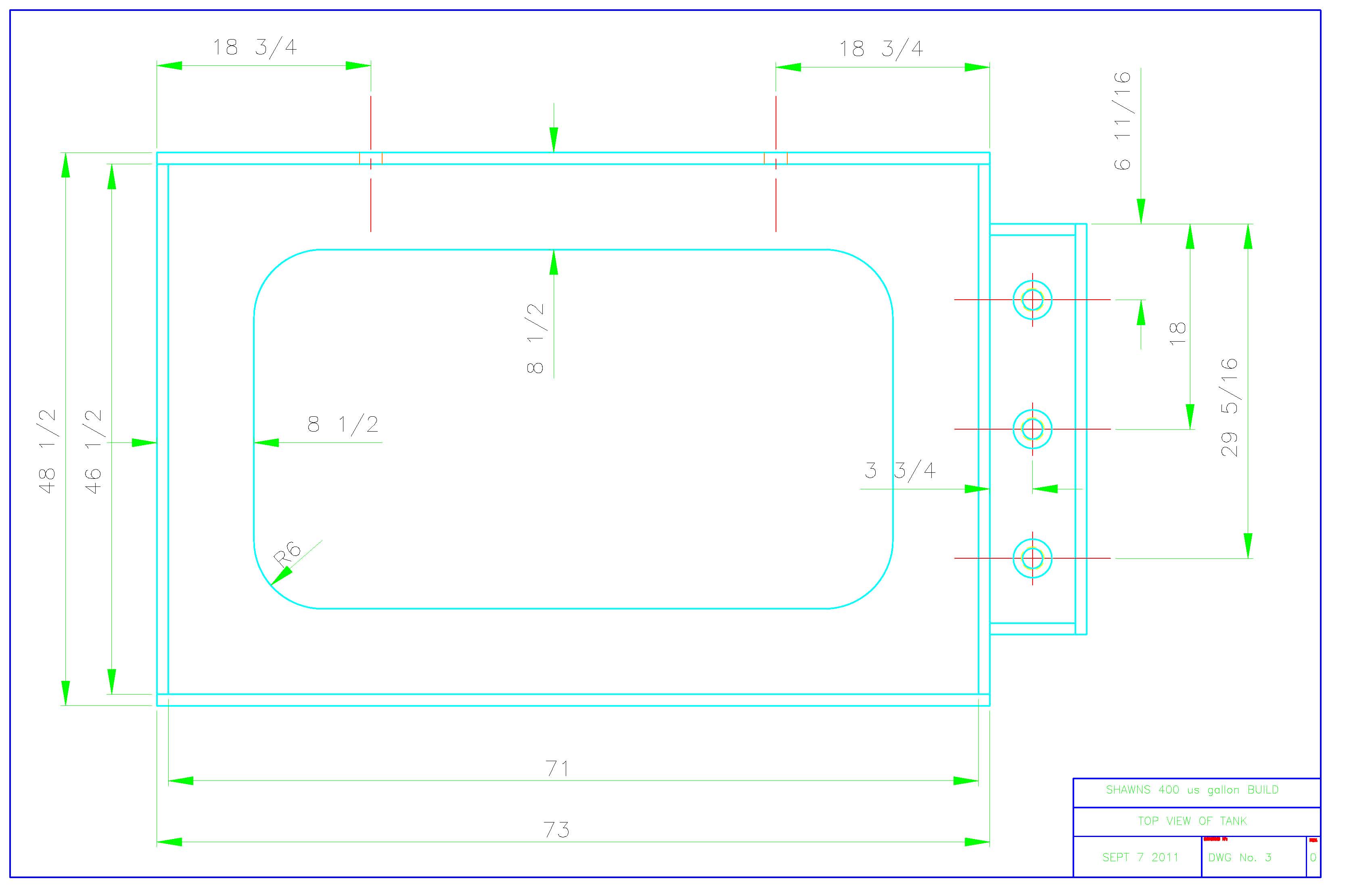
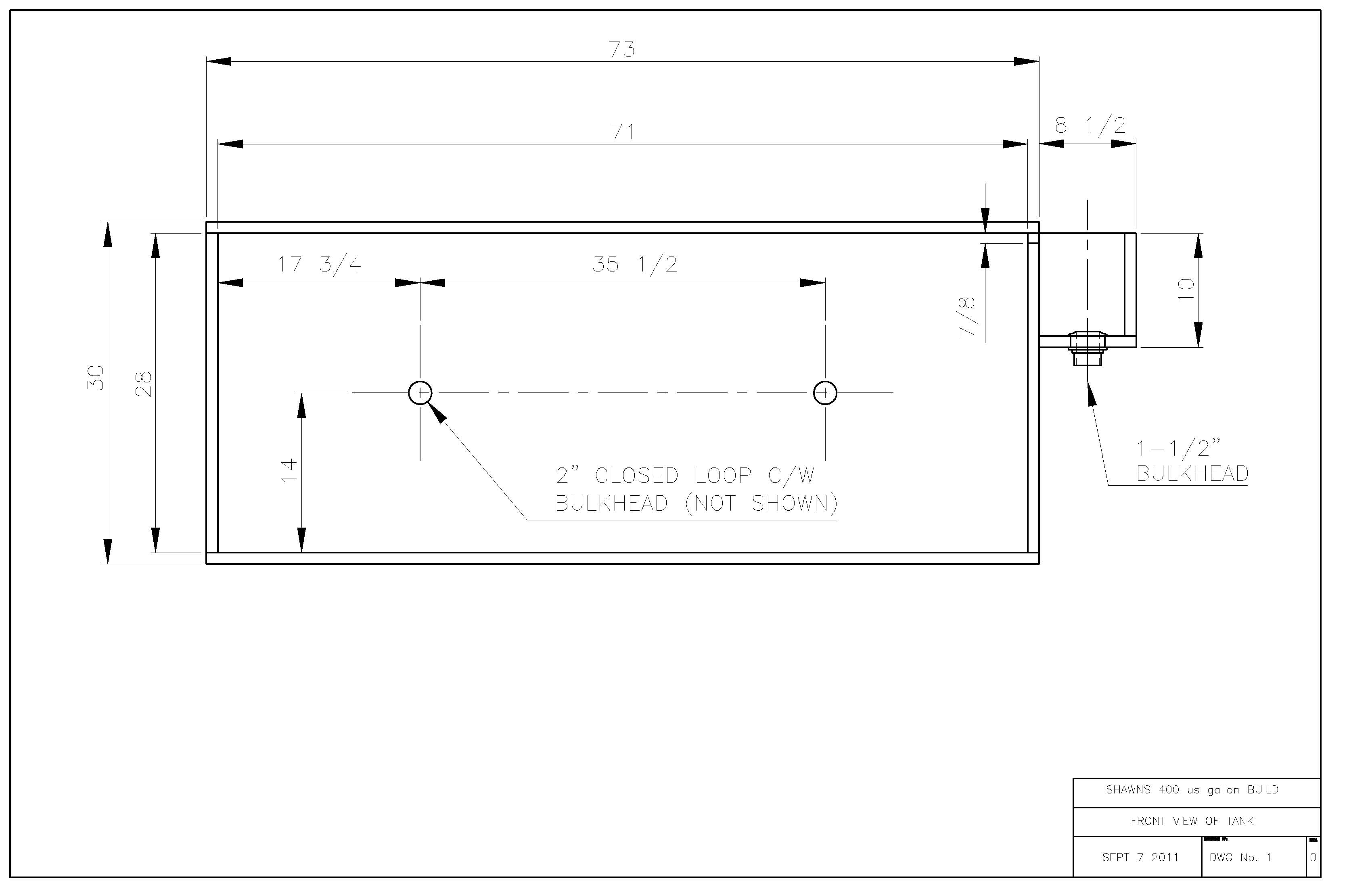
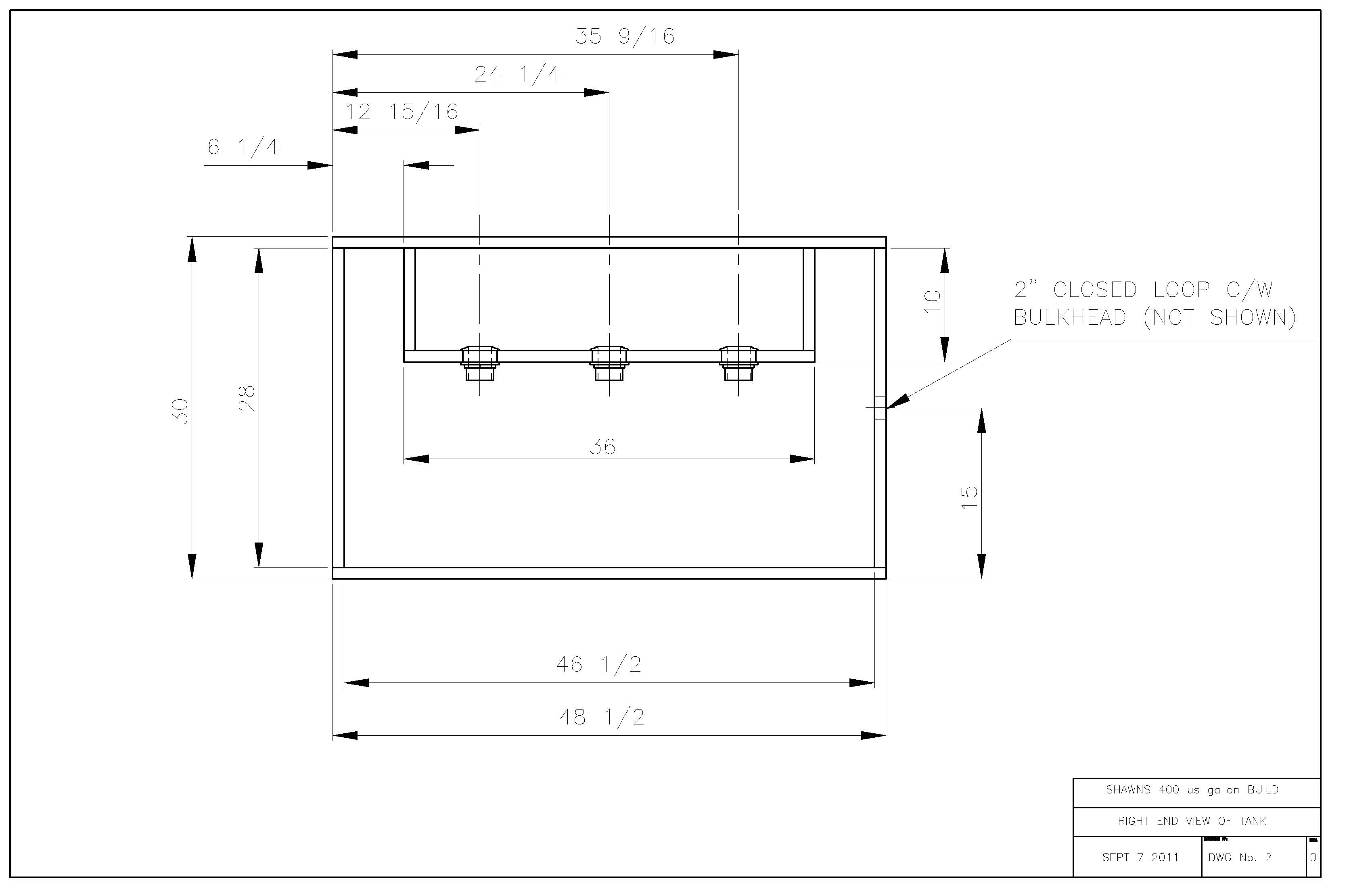
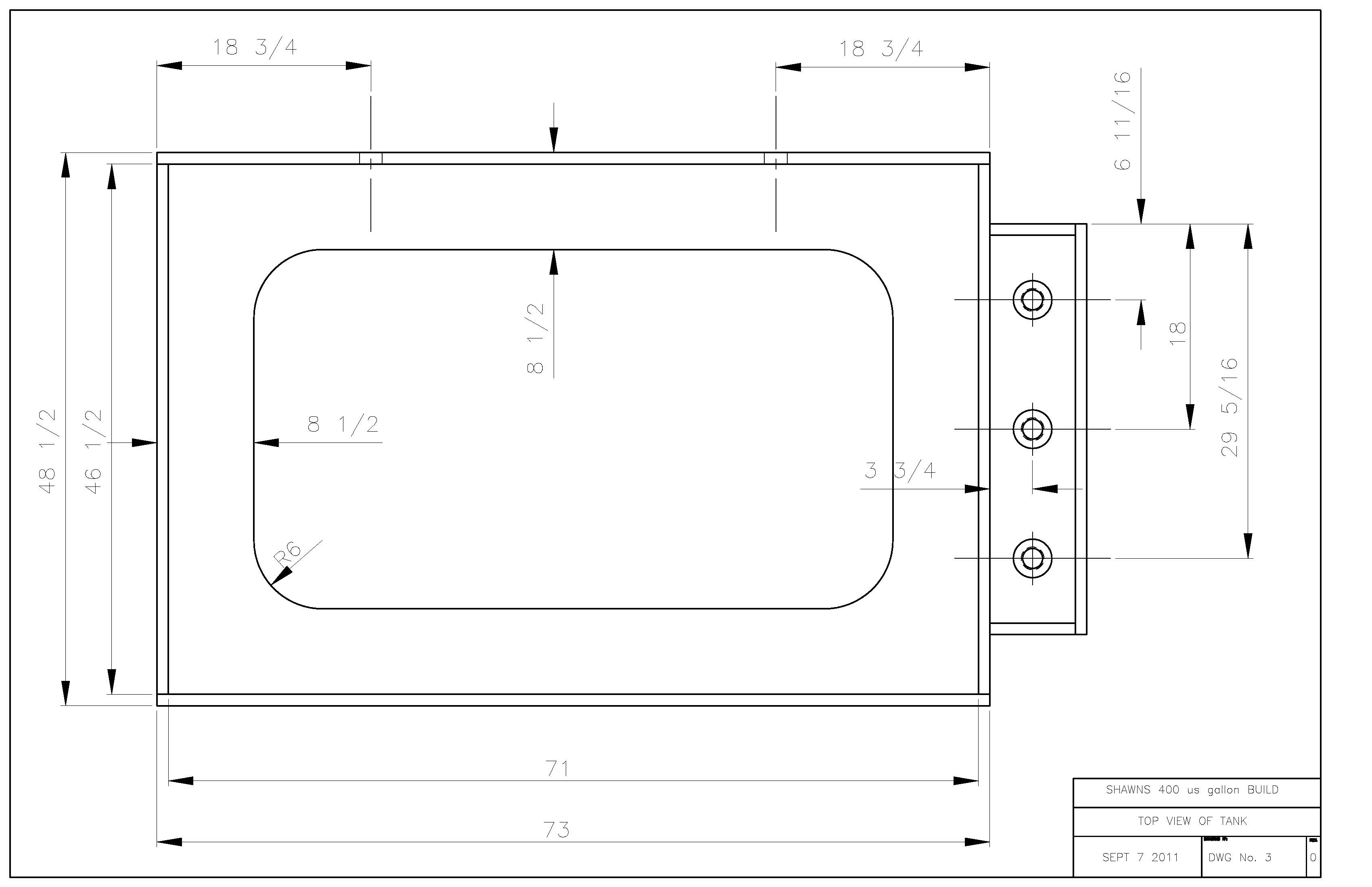
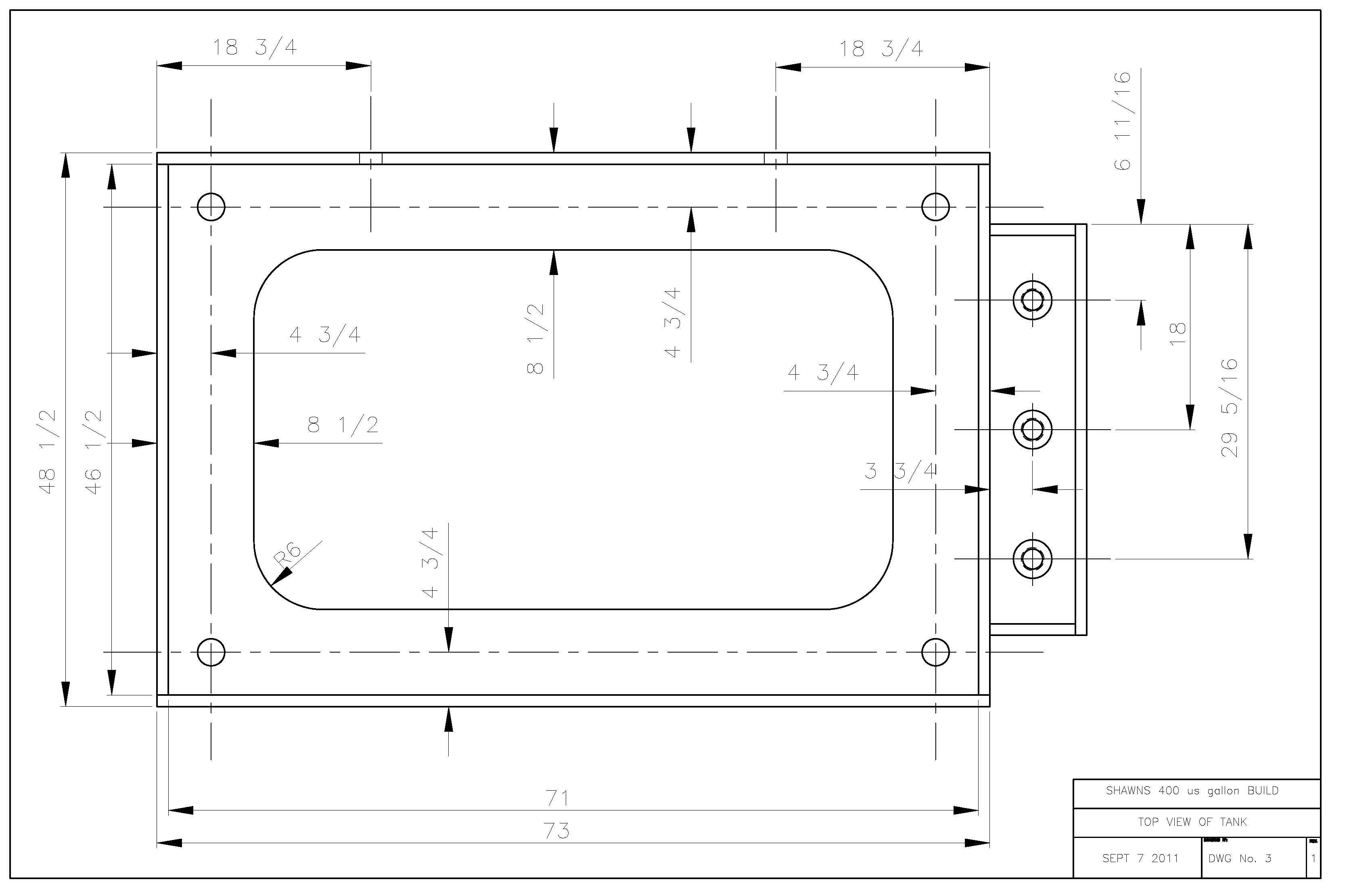
Totally awesome Al........Looking at the overflow box, and I just took measurements on the dang thing, and I'm pretty sure I didn't give them to you this morning, but they are dead on accurate with what I have drilled......How do you like the radius layout of the euro bracing????
Let me know what other measurements you need.......
 

al&burke

Active Member
Here are the same drawings but not in color you might be able to read them better SHawn, if you click on them they get bigger.
 

acrylic51

Active Member
Sorry for the slow response Al....but again Thank You!!!!!

Right now I'm planning on 1" schedule 80 bulkheads for the CL in the bottom of the tank......That could change after I get with Paul from OceansMotions and see if it's possible to have the OM 8Way built with 1 1/2" outlets instead of the standard 1".......
 

acrylic51

Active Member

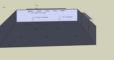
Ok.....Here's my crude layout from the begining of the build.......Things have changed a bit as most of us know....The external overflow has been moved from the back wall to the right side panel.....(if your looking at the pic from left to right). On the back panel the only changes are there won't be any slots/slits as shown in the pic, but the 2" CL drains will still be in the same location, and thanks to Al's drawings; it gives me exact measurements for drilling........
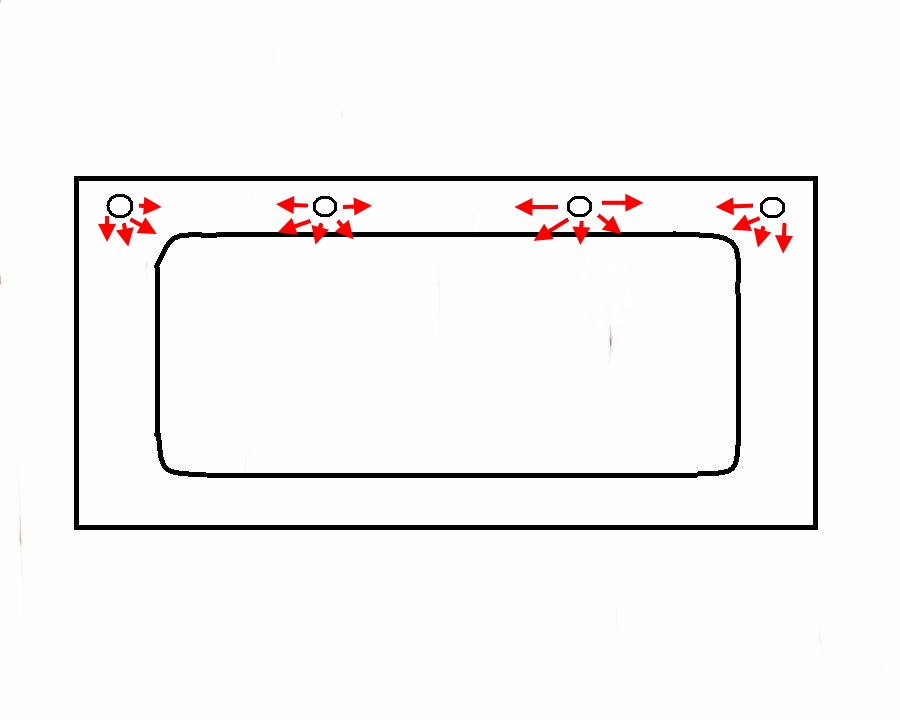
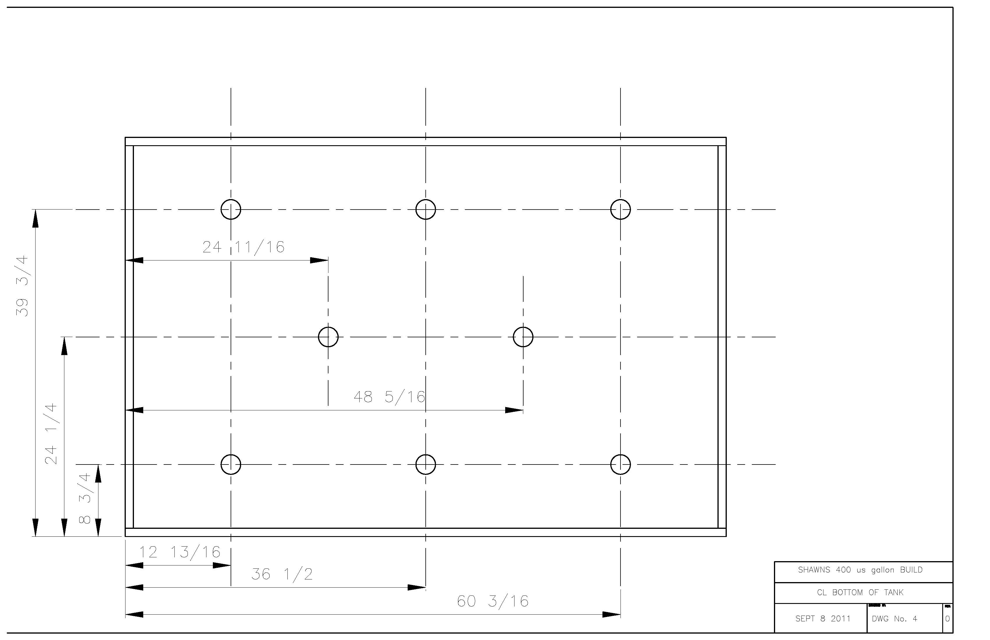
Moving on to the bulkheads in the bottom of the panel.....As you can see in the pic there are a total of 8 bulkheads. The bulkheads that are somewhat aligned behind each other will stay in the general location, but the odd ball 2 in the center by themselves will not be drilled in the design......

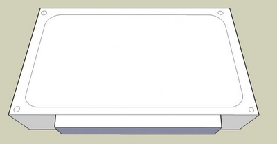
In this pic you get the overall general idea that bulkheads will be placed in the euro bracing......I've chosen this option for a couple reasons....1 to keep the viewing area of the tank as clean as possible and the other is mounting the returns on the side panel by the overflow has them sitting lower in the water line, and thus creating possibly more back siphon to the sump in the event of a power outage......In this next bit were going to talk a bit about both the return from the sump and CL returns.....Hang on to your seats!!!!!!!

A major goal in this setup is to maximize flow without adding tons of PH's to the DT......Looking at the above pic left to right you notice 2 bulkhead holes drilled in the corners of the euro bracing....With the proposed plan those holes would still be in the euro bracing, but they would be moved inward roughly 12" or more from the corners.....These would be the returns from the sump......A major goal or plan is to create the "barrel roll effect". I want to try to increase or maximize flow to keep detrius suspend in the water column so it can be effectively removed from the DT. These "returns" from the tank will be 1 1/2". The return pump will be the Reeflo Hybrid Snapper/Dart pump. These 2 returns will be split into 2 nozzles.....These nozzles will be pointed or aim downward towards the bottom of the tank, where (hopefully) the water will hit the bottom of the side wall/bottom and roll towards the opposite side of the tank......A lot of things can and do affect water flow within the DT, and rock work being the biggest. The rock will be pinned with clear acrylic rod, and will not sit directly on the tank bottom therefore allowing water to easily flow underneath the rock work.
Ok!!!!!! With the water entering the DT from the right top side of the euro bracing being forced down and towards the left bottom of the tank; this is where the CL bulkheads will come into play......The bulkheads on the bottom will be connected to an OM. Version 3 is what I'm planning for the OM. The first 2 bulkheads; which again will be split into 2 nozzles. In theory with the water being forced downward and towards the left under the rock work, the first 4 nozzles will fire, and continue to force water across the bottom of the tank....The nozzles will be aimed towards the front panel a bit, down the center, and the back nozzles will be aimed towards the center of the tank and towards the back wall as well; giving a broad coverage of the bottom of the tank. As the water is forced across the bottom towards the left, the next set of nozzles from the CL will fire, continuing the flow across the bottom and then the next 4 nozzles will fire again keeping the momentum moving till it reaches the far wall and deflects (hopefully upward) where the last set of nozzles drilled in the top euro bracing will fire forcing the water back towards the overflow......

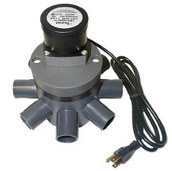
This is the 8Way OM and each port will be connected to bulkheads in the bottom of the tank and the top far bulkheads in the euro bracing......

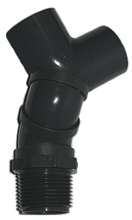
Theres are the nozzles that will be connected to the bulkheads in the bottom of the tank, and will have to configure some loc line to the ends to get the flow exactly where I want it......but gives you a general idea.......

These are OM revs and is a thought of using on the far left top euro bracing to fire water back towards the overflow on the other end of the tank. The reason I like these as an option is that at each firing, they drop down into the water and fire, and then pop up, and the next time they drop down rotating a bit and firing; therefore you always have a changing angle the water is being pushed back across the tank water surface. I will have plenty of pump as well to plumb dual returns from the return pump on this side of the tank as well as on the other side of the tank.....
Ok guys.....I've laid it out there for you, and wanting to know your thoughts and opinions on this portion so far.....There's still another twist to the CL...Meaning there will be a 2nd CL system. Also another idea I've been contemplating is using/building a VFD pump, but unfortunately I can't link the info, but anyone wanting more info just PM and I'll fill you in......
Again thoughts and critiques!!!!!!!
 

acrylic51

Active Member
Quote:
Originally Posted by Al&Burke http:///t/376802/415-gallon-plywood-tank-build/1100#post_3414359

Again very nice Al....... Sorry, but a couple changes......
In the first drawing can we move the bulkhead holes that are in the corner inward towards the center of the side panel 12 1/2"......Possibly a bit more, but measuring it out on the tank 12 1/2" seems to get me in the general location I like the holes....
On the second drawing can we remove the bulkhead holes in the center. Those bulkheads are located at 24 11/16" & bulkhead @ 48 5/16". These aren't going to be drilled for the final CL.
 
Top