Neptunes 125 Reef Diary.

king_neptune

Active Member
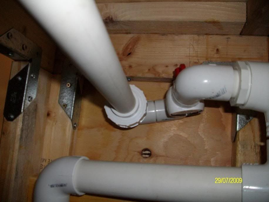
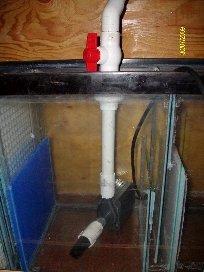
thanks for the advice. Ill play around with the durso and try various sized holes. I have some model air plane control rod tubes that are pretty long. I was going to stuff them down the durso stand to make the bubbles breath a little deeper into the pipe, not just an inch from the top.
Wasnt sure if it would help with noise...but I can see what works.
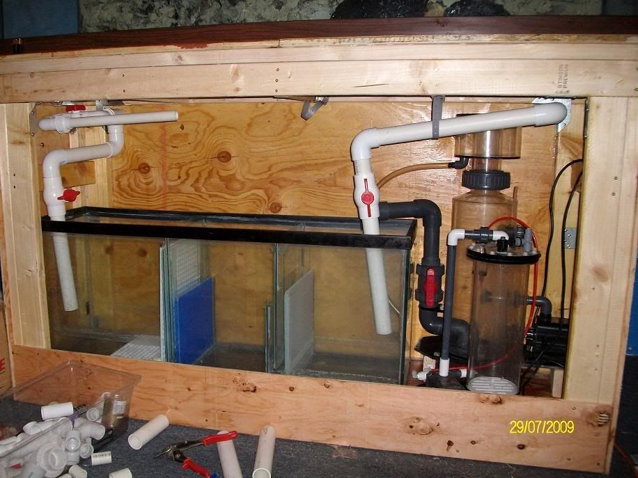
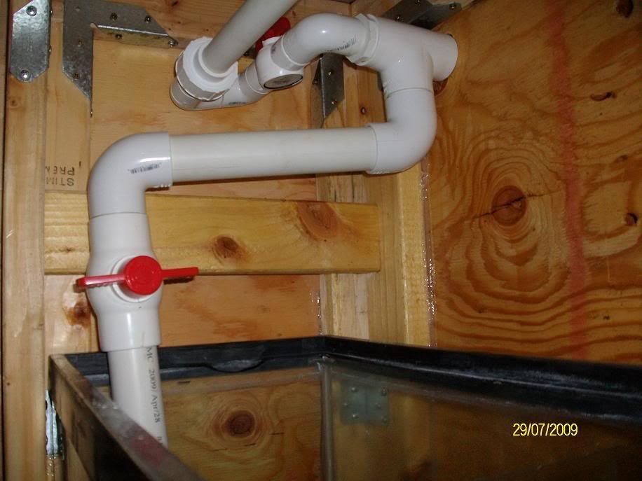
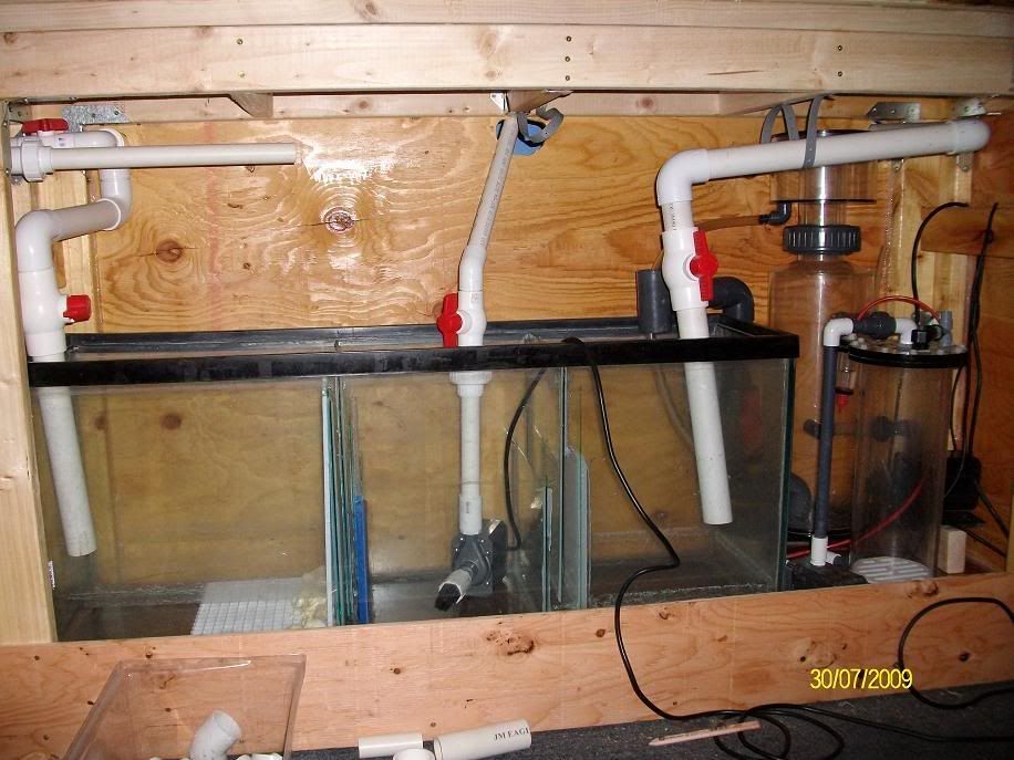
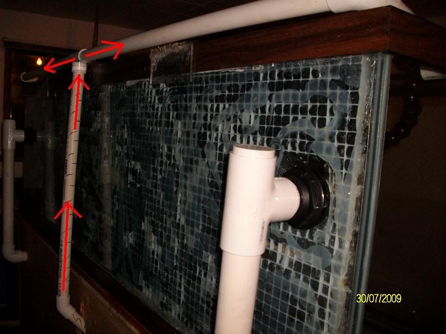
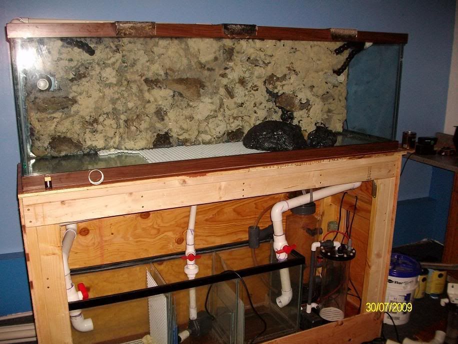
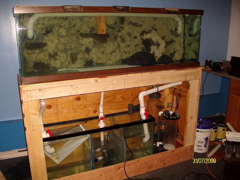
Ideally I want a slow moving fuge. Although 400 would be the really low end, if I could get a tad more that would be nice. Say 500...but definitely no more than 600 per side. I don't want water racing through the sump. I just chose 1.5" pipes to drain on the left and right because I felt this would be the most likely way to achieve this goal. However....in hindsight...maybe 2" would have been better. Too late now, I drilled the bulkheads.
 

deejeff442

Active Member
a durso should be easy to set up where you have the holes.
you always want the drains to be able to take more water flow than your pump is putting out in case something partially plugs them.
i remember when i (so i thought)invented a spark plug whistle to find top dead center on an engine by yourself.thought i was going to make a ton on it.well a year or so went by and i didnt get around to it.then saw a similar tool just like it selling in a magazine for $50 .
$2 to make it.well at least i know it was a good idea.
 

king_neptune

Active Member
Put in the foam wall just now. Got it braced up with some wood to hold it in while the silicone dries. I get started on the plumbing a little later after a nap and a shower...boy oh boy its hot today.


king_neptune

Active Member
Originally Posted by fishkid13
http:///forum/post/3097342
Looken Good Nep. That one board looks like it is going to scatch the glass.
Nope. Glass is fine. I'm not pitting a lot of pressure. Just enough to take the shape of the foam wall and press it flat against the back.

Added acrylic braces and welded them into place with a plastic bonding epoxy. Then I Torched em and folded them over to add a little more strength. Don't worry about the ugly acrylic work. Ill sand it over and take out the scorch marks. Next time I head to town Ill by an assorted variety of sand paper. Basically you start with 120 and work your way to 3600. Hitting about a dozen types in between till you end up with a piece that is like new. The flaps themselves are ugly So Ill eventually make a nice skirt at the top to match whatever I do with the stand. But for now I'm going functionality over form.
Notice I left the middle bracer unbent in the back.Its still welded on...but I didn't fold it over. I debated this...and decided to leave it in place. Ill drill a 1" hole in it and use that piece to hold the return line that comes up the center and over the top.
 

king_neptune

Active Member
Began the plumbing.... having some minor frustrations.
Skimmer is an absolute BEAST!! I can only fit it inside with the calcium reactor. If I cut the base plate off and turn the pump 90 degrees...but this means I alter the flow of the water. Will that change things? And doing it this way is cramped at best.

And that means the Skimmer would have to be modded by turning the pump sideways, and the remaining excess base plate trimmer off. Can the reactor run inside the sump ok? I believe it was a wet/dry( I ran it submerged for 24hours in vinegar)...or does that not exist on calcium reactors?
One of them has to go in the sump, or I have to mod the skimmer, so they can both fit in the pocket

With the reactor inside the sump I gain room for the skimmer to site sideways, but lose real estate in the fuge area.

Now that the skimmer is outside....its too short:

I can extend the drain:

But doesn't that cause the water to raise all the way into the collection cup? OK so then I raise the skimmer on blocks...oh wait:

This has to get cut out now.
Sigh...I'm too tired. I'm going bed, and Ill struggle with this later this afternoon when I wake up. If someone comes up with a solution while I sleep lemme know. Thanks.
 

king_neptune

Active Member
Ok I think I got a workable solution.
Build a platform raise the skimmer then place the carbon reactor underneath.

Its a little cramped. And the collection cup sits kinda high. And I'll have to work the plumbing around it, but I think Ill be ok.
The other option is to cut out the cross member and put the skimmer a little lower.
 

posiden

Active Member
Have you disclosed your top secret drain system you have in mind and I have missed it???
How do you plan to controll the flow to your skimmer?? You don't want a lot of flow through it or your contact time will suck and it wont work very efficently.
I ask cause I am interested in how you plan to plumb this thing out. I typed up a nice reply to you in the scrubber thread and then I deleted it. I don't think that is the thread to get detailed on your plumbing. This is the place.
 

king_neptune

Active Member
^^
1: ya, my super top secret drain was the previous page...turns out im not so special

there are plenty of people that have done it. on the plus side it means I can learn from thier designs, and it is a workable drainage system.
2: skimmer has its own pump for feeding it, and that will sit inside the sump. The skimmer requires 600gph flow, and that's what the pump is for. But...your definitely right, I will put a flow valve on the feed line into the skimmer just in case, i want to reduce it to get a better mixture. However I'm really hoping I wont be relying on the skimmer as a primary means of filtration. I'm hopping the turf scrubber will do that.
And speak of the devil^^

That's how I got the concept...this was posted by santamonica a while back. I saved it and been thinking about it for some time.
The logic is that I can adjust the flow to the scrubber by opening or closing it, and at the same time opening and closing the main valve down below to create back pressure, which in turn will force more water through the 1" lines.
Bottom line, I wand a slow moving fuge, I don't want alot of water racing through it. If it was 400, I would be dissapointed. But If I can hit 600 on each side, Ill be plenty happy. From there I can always throttle it back. Same with the mag 1800, I will put a control valve on that as well to keep it throttled down.
 

posiden

Active Member
Looking at that picture, I think I would reverse the two. Choke down the flow to the scrubber and let the drain take the rest. In this manner you will not need the optional fail drain off the side of the scrubber. It will be your drain. I will see if I can figure out how to draw stuff on here.
Here you go.
 

king_neptune

Active Member
two fold problem. neither is really critcle. but they do present themselves:
1. Now I have no way to shut off the scrubber...ill be splashing everywhere while i try to attach/remove the pipe for cleaning.
2. I have no way to reduce the flow incase the scrubber is getting too much. You dont want to high of flow...just enough to film the screen...not blast it.
Still, I do appreciate the input, I weigh everything I gather so thank you for the time you took. I'm not going to plumb it in permanent yet. I still want to spend another day reading and listening to input all around.

[hr]
Hear is the drain lines, nothing is glued in...just dry fitted to demo it before I choose a final.

Stand pipes:

The cap i am considering leaving unglued...in case I want to ever do maintenance. They are a really really tight fit, so it wont be easy to pull off. Also I'm putting a sliding airline. It is made from model airplane control rod housing. It resembles a 3ft long straw, and stiff. The theory behind it is I can slide the tube up and down the length of the durso to "Tweak" where my air bubbles hit the water. Therefore adjusting my noise. Also I can cap these with a valve to adjust the flow of air.
I worked out my space problem with that monster skimmer:

I can fit skimmer,calcium reactor,and probably a 20-35lb Co2 canister.
I changed up the oposite side of the sump a little:

1.5" Flow valve is in a different spot, this made more room for the screen to hang closer to the edge of the sump. Also tweaked the plumbing on the scrubber a little as well.


Adding this "U-Turn", gave me a good amount of space to work with. Originally I was limiting myself to the length of my screen pipe. Now I can have a screen run the length of the fuge chamber. AND allow me a union coupling to remove it for easy maintenance/upgraded screens.
The draw back is this also restricts flow a bit, but I can compensate via larger holes in the screen pipe...or adjusting the flow valve on the primary drain below.
 

jas1

Member
LOL!!! You should see my garage at the moment
Very nice job by the way
Thanx for all the close-ups of your plumbing.
 

king_neptune

Active Member
Dry plumbed the return system to demo it before I glue it in.

Its a Mag18, I immediately went from 3/4" to 1" and Put in a coupler for easy removal/cleaning ect. Then a flow valve to control the throttle. After that I ran the 1" line at a 45 degree angle to the outside of the tank.

I drilled a hole to allow the "T" fitting to slip through the acrylic I left over hanging. This will help keep the return line locked down.

I branched out to either side where I will have it go back down to 3/4" loclines.

Ill fasten it into place with epoxy resin tomorrow. Plus I have to go to the hardware store and pick up coupling to convert from 1" to 3/4" threaded, so I can place in the loc lines.
I have a question about the Return pump...is it ok to have it site on glass like that? or should I pad it somehow to keep vibrations down? Also does it need to be in filter sock of some kind?
 

fishkid13

Active Member
My current return pump was very load once it touched the glass so I stuck some pad underneath it. Looks like it is coming along.
Its me, you, and Jas1 to see you can get their tank up and running the fastest.
 

king_neptune

Active Member
I'm stuck till i get the RO unit installed, and I cant do that till the plumbing is done, and that is held up by the floor not being poured. And there is my holdup...i cant do that till he orders the gravel.
My Dad is the chef procrastinator, there is no other. His 29 gal nano has been sitting like this for 2 months:

And before I did even that much..it was sitting in the garage in a box for 6. I thought that if I at least get it out of the box and on a counter he would do something. Believe me, I want this tank done. Dont even get me started on the homebuilt airplane thats been sitting int the garage for 15years. He doesn't even have the tail stabalizers done.
But Realistically...it can likely be another month before I get him off his @$$.
"Don't worry, its not going any where. Stop trying to rush things."
FUDGE!! I mean WTF!! I want to scream so bad. This tank would never get done if I wasn't pestering him to hurry up and plumb the RO-UNIT.
 

king_neptune

Active Member

ALmost done!! Just need to get the over flow bar. Gonna be the hardest part. If i dont get it perfectly level im in trouble^^
 

king_neptune

Active Member
Freshwater test:

Partial success...had to stop and drain half the DT to adjust the flow bar, it was too high. Glad I didn't glue it in.
I think I might remove it altogether and put a 2" bar, with adapters down to 1.5 instead.
I get OK
flow from it, It handles the Mag18 at full throttle. But it doesn't seem like the mag pushes much water...maybe 1800GPH isn't a whole lot of flow. My garden hose couldn't keep up with it when I was filling, had to ween the pump down to about %60.
I'm re doing the re-turn line. Gonna have just one "Y" locline at the center top. Instead of that gaudy pipe spanning the rim of the tank. Having 2 "Y"'s didn't seem put out much pressure. Cutting it down to one might help push the water a little harder. With the mag at full throttle I still cant drain the sump, the main lines refilling it fast. So either my Mag is broken and weak...not likely. It either works or it doesn't. I can keep up with 1800GPH flow via my two 1.5" lines.
Skims mainly from the ends and tapers off towards the middle. I will first experiment by re-cutting a new bar with a different pattern to the slits. I doubled up on the middle with vertical slits...but evidently that wasn't enough to compensate.
I played with the valves a bunch even got the durso stand to back up and spill a half gallon before I realized what I had done^^
The middle of the bar was sagging so I propped it up with a piece of wood. When I wake up Ill cut another piece and see how the drainage goes.
The surface skimming was pulling a thin layer off the top as far as a foot away near the ends, but towards the middle there was a film floating just a few inches away and it slowly was pulling it in.
Either increasing the size of the pipe will help....or changing the pattern of the clits. I'm not too sure a 2" will do anything more, but adjusting the pattern on the next bar might. Ill have even less slits on the ends than before...and more in the middle. Too bad since i spent a good hour shaping and filing the holes smooth
At any rate Im tired and am going to bed. If you got any ideas while I sleep Id like to hear them.
 

spanko

Active Member
So have you rotated the overflow pipe so that the opening is topside? If so here are a couple of options;
1. To prevent sagging, not sure which schedule pvc you are using but there are:
Schedule 40 which is pretty normally available and 1 1/2 has;
O.D. of 1.90
I.D. of 1.590
Min wall of .145
Schedule 80 at 1 1/2;
O.D of 1.90
I.D. of 1.476
Min wall of .200
So you can see here the schedule 80 pipe will be "stiffer" and probably not bow in the middle.
For the overflow slit, I would cut the slit a tad wider with no "vertical" slits as you call them. As I look at the picture of the one I posted for you the slit is just cut in the pipe along the length but looks to be wider than yours does.
 
Top