Originally Posted by SCSInet
http:///forum/post/2450532
Sump
With my sump, I had to make concessions that I am not happy with, but it is what it is.
I didn't have a suitable location for a fish room, so I had to make the sump much smaller than I wanted to. I also really wanted a 3 compartment design where the skimmer is set up so it cannot pull water from the fuge, but I had to give that up as well.
Anyway, the sump is roughly 36x18, constructed out of 3/8" cell cast arcrylic. I mapped out the layout of everything on the computer so I knew exactly what sizes to cut everything, which made everything MUCH easier to put together. It also allowed me to lay out the pieces on the 4x8 foot sheet on the computer, and orient them so as to allow the least number of cuts and most efficient use of the material (least waste).
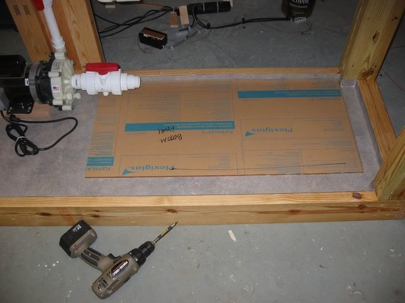
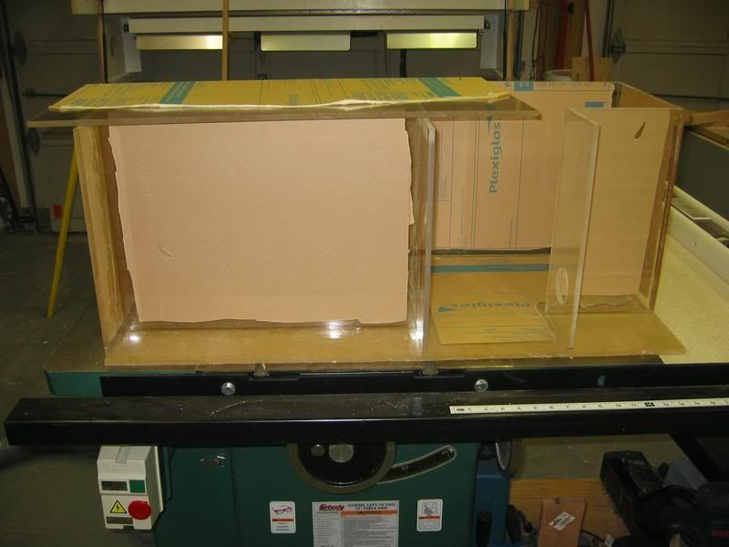
I cut out the bottom and laid it out in the stand to see how everything would fit.
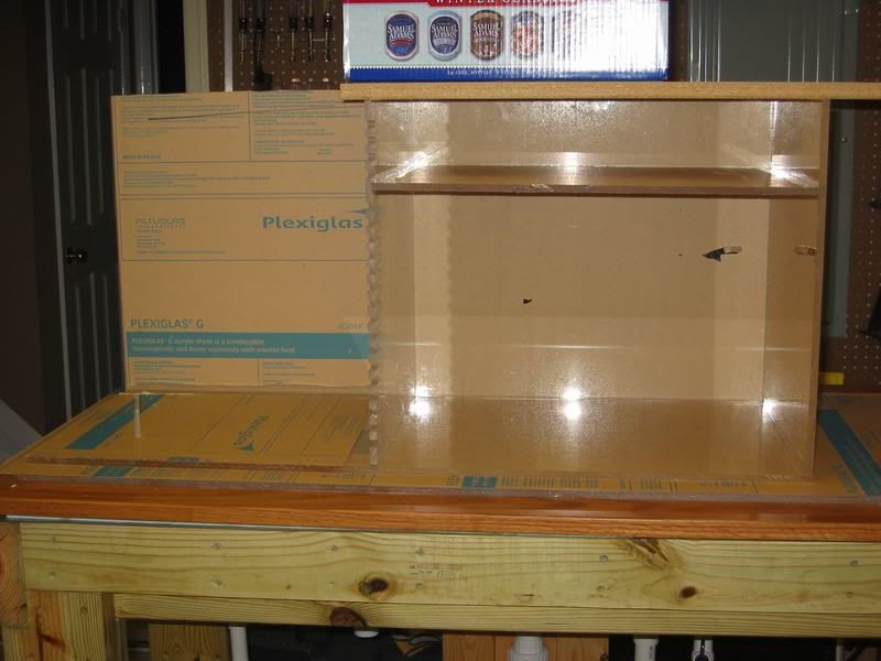
The sump is to have 3 compartments. A fuge, a return, and a heater compartment. The heater compartment is designed to maximize flow across the heaters, and prevent them from ever being run dry. I used to put heaters in the return section, but if I let evaporation get away from me, the heaters would be exposed to air. I wasn't gonna have that this time.
At first, the pump was supposed to be mounted with (2) 90 degree fittings with the valve in between, but I read on this board that the sequence pumps pull so hard they don't do well with bends on their intake, so I switched to a union-ball-valve and integrated an inside corner into the sump to allow room for it. You'll see what I mean as we go...
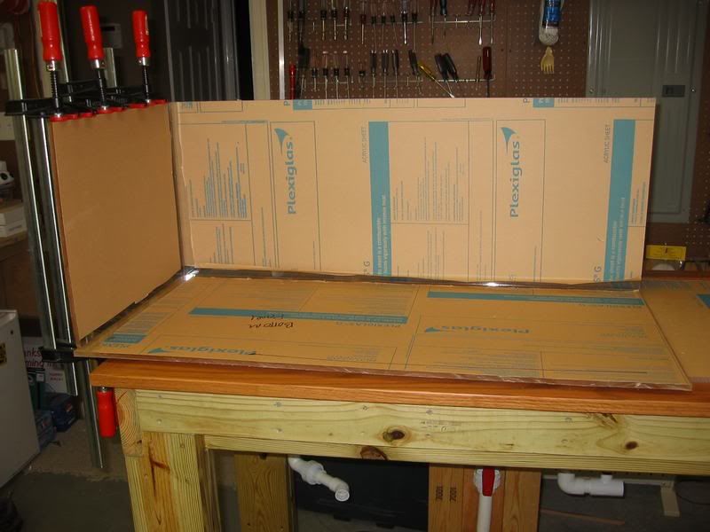
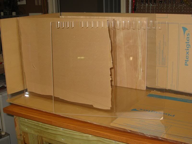
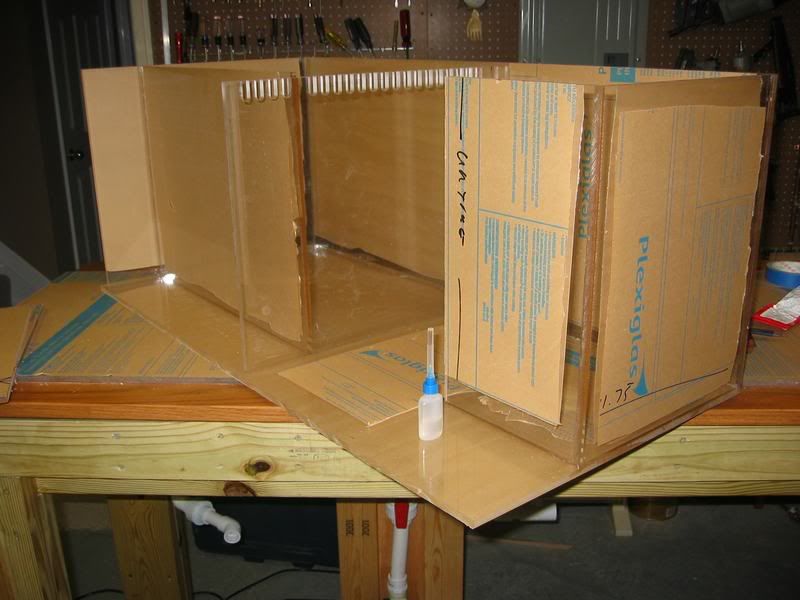
I started assembling sides....
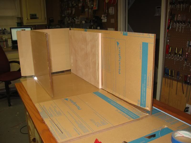
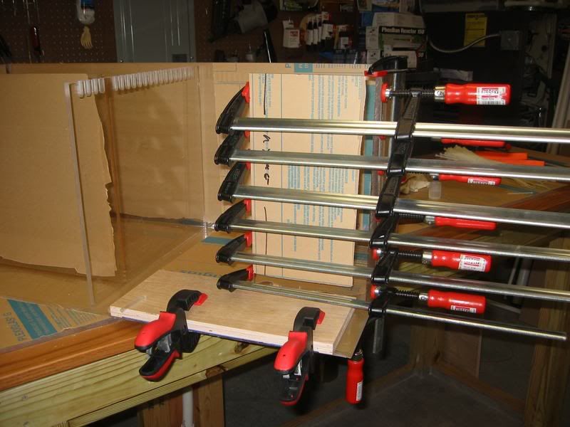
Next, I cut a spacer block out of plywood scrap to sit inside one compartment. This piece was cut to the same size as the mid-wall near it, so that I could place another baffle into position and have it square up perfectly, as well as support the piece with the sump turned up on end so I could weigh it down when welding the seams.
The next piece to install was a baffle that divides the fuge and heater sections from the return section.
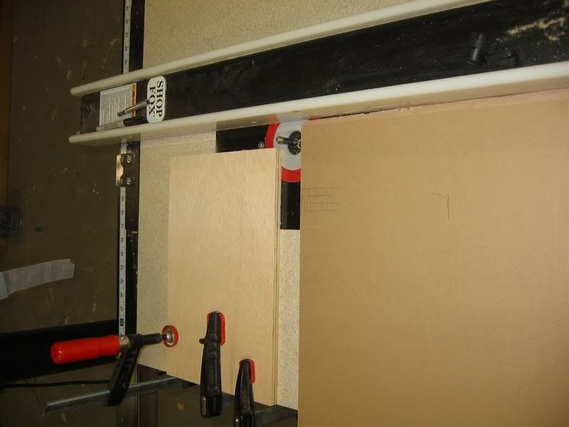
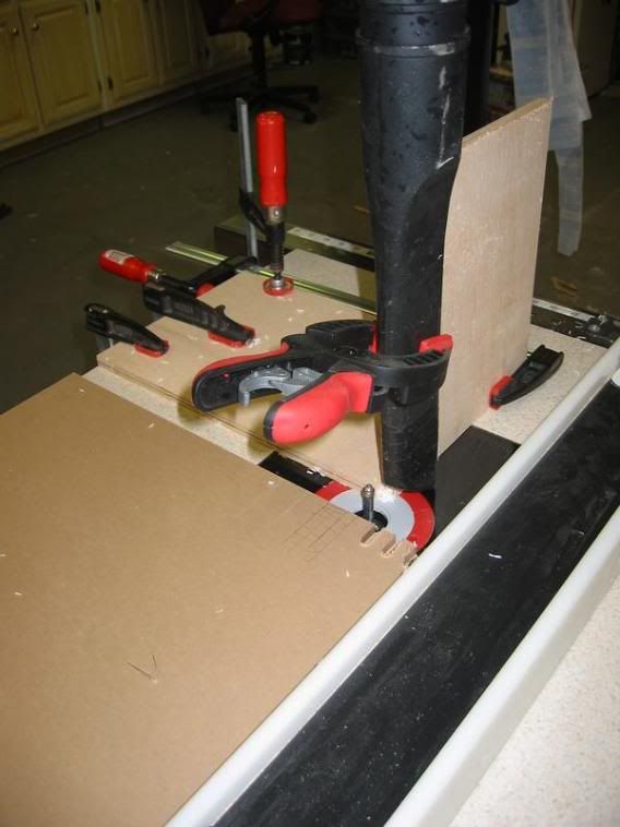
To cut the teeth in the baffle, I set up my router table with a depth stop, and arranged it so that I could move my saw fence 3/4" after each cut, then simply ride the fence and plunch into the bit unitl I hit the stop, and acheive perfect, consistent teeth.
I set up a shop vac to collect chips from above, and the dust collector was set up underneath to pull them down. Otherwise, chips would build up and affect the stop depth.
I remember that elbow you had planned on the intake side. Sorry to cause the reengineering, but I think you are better off in the long run you did!
Warren


